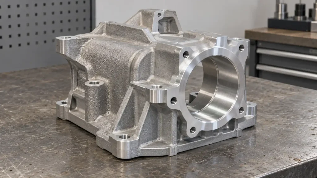
Direct answer. A cast-aluminum housing should not be quoted or inspected as if every as-cast surface were a finished datum. First define the casting route and drawing revision, machining stock at each functional face, temporary locating strategy, final functional datums, and the acceptance rule for porosity exposed by machining. The casting supplier, machining supplier and design owner must agree on who owns each feature and when it is inspected. A perfect toolpath cannot create material where the raw casting has insufficient stock.
Separate the cast shape from the finished interfaces
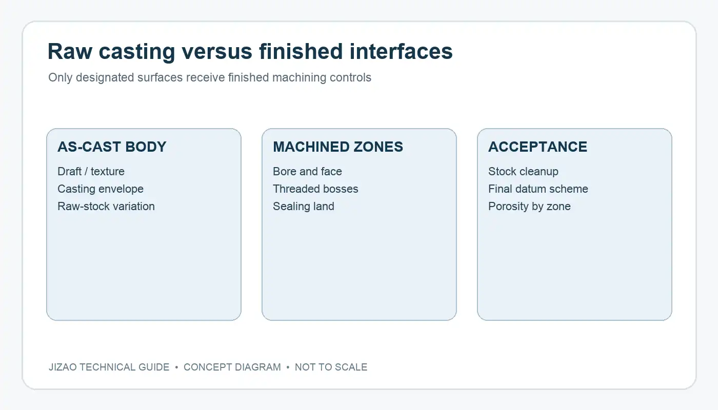
Casting provides the near-net body, ribs and bosses; machining establishes selected bores, mounting faces, threads and sealing interfaces. The model should distinguish as-cast surfaces from machined surfaces, preferably in a clearly controlled drawing or MBD definition. Label any surfaces that are allowed to retain draft, parting-line evidence or casting texture. Conversely, assign final size, form, finish and datum relationships to the features that actually locate or seal the assembly.
Do not put an unrealistically tight finished tolerance on a surface that will never be cut. Conversely, a raw casting tolerance cannot stand in for a bearing-seat or gasket-face tolerance after machining. The Aluminum Association publishes separate casting guidance for tolerances and allowances; the applicable values depend on casting process and specification, so the design package should identify its chosen process rather than borrowing a universal allowance [1].
Make stock allowance a feature-by-feature decision
Stock allowance must absorb expected casting variation, parting and gate location, core shift where relevant, and the machining setup's positioning uncertainty while leaving enough material to clean up functional surfaces. More stock is not always safer: it can lengthen machining, expose subsurface porosity, thin a wall, or distort a light casting during material removal. Review each bore and pad on the least-favorable raw-casting condition, not only on a nominal CAD overlay.
An effective RFQ package includes the raw casting model or drawing, the finished model or drawing, datum targets, anticipated gate/parting locations and a note on whether the raw blank is customer-supplied. If no raw-casting envelope is available, a machining quote should identify stock and yield assumptions rather than promise unconditional cleanup. A first-article check can compare actual casting variation with the process plan before production fixtures are finalized.
Do not confuse fixture locators with functional datums
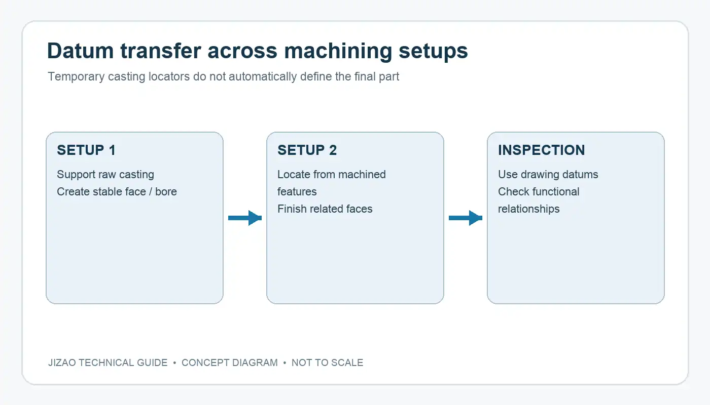
An irregular casting may need temporary pads, adjustable supports or cast datum targets for the first machining setup. Those locators help prevent rocking and distribute clamping; they do not automatically become the final drawing datums. A common route is to create a machined face or bore in an initial setup, then relocate from those controlled features for subsequent operations. The exact sequence depends on rigidity, accessible material and the functional datum scheme.
When a multi-face housing is reoriented, record which surfaces and holes are used to re-establish location. If a critical bore and its mating face are cut in different setups, the drawing must define their relationship and the inspection plan must be able to measure it. Five-axis access can consolidate some operations, but a machine's axes do not resolve unstable support, inconsistent cast stock or ambiguous datums. For the distinction between design and inspection datums, see our multi-face datum guide.
Plan for porosity revealed on a finished surface
Porosity is not a single defect with one acceptance rule. Its origin and distribution depend on the casting process and local geometry; a surface that looks sound before machining may reveal a void after cutting. The North American Die Casting Association treats porosity as a process-and-design issue, and industrial metrology guidance describes internal defects that are not visible from the exterior [2][3]. A machined void on an internal nonfunctional wall may be acceptable while the same void on a seal land, threaded boss or pressure boundary may be unacceptable.
Define the critical zones before production. For each, state the allowable indication or acceptance standard, inspection method, sampling level and disposition path. If leak-tightness is required, identify the boundary and test state. Do not use a blanket “no porosity” note unless the design team has established a verifiable requirement and a feasible supply route. CT, visual inspection and leak testing reveal different properties; none should be treated as an interchangeable universal proof.
Impregnation, welding or other repair is a design and process decision, not an automatic shop remedy. If permitted, the drawing and purchase terms should state the approved repair scope, traceability and post-repair verification. If not permitted, say so.
A drawing-and-RFQ checklist
Send the alloy and casting process, controlled raw and finished definitions, machined-surface map, final datum scheme, critical bore/face tolerances, required surface condition, porosity acceptance zones, repair policy and inspection expectations. Ask the casting and machining parties to review whether all critical faces have enough stock and whether fixture contact will damage thin ribs. If the component is a pressure or sealing housing, include the service and test boundary without assuming the machining supplier owns the complete assembly test.
The practical question is not “Can CNC machine a casting?” but “Can this casting route, fixture plan and acceptance scheme produce the required interfaces at a controllable yield?” For a drawing review, contact JIZAO with nonconfidential requirements; any part-specific capability must be confirmed after review.
Sources
- The Aluminum Association, standards for aluminum sand and permanent-mold castings — scope of process-specific casting tolerance and allowance guidance.
- NADCA, How Do You Tackle Porosity? — die-casting porosity causes and process controls.
- ZEISS, light-metal casting metrology — inspection context for internal and surface defects.
Images are conceptual engineering illustrations. They are not customer parts, JIZAO production records or inspection evidence.






