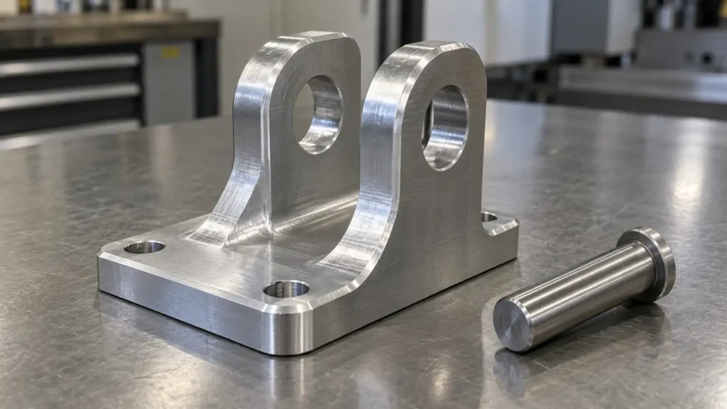
A clevis bracket connects a mounting structure to a pivoting eye, rod end or bushing through a pin. Two fork ears, their shared pin axis, the slot between them and the mounting face have to work as one assembly. Merely specifying “two Ø holes” leaves unanswered whether the pin can pass through both ears, whether the mating eye has adequate side clearance, and whether the bracket can be inspected after the jaws are released.
The featured bracket and loose pin are a conceptual engineering visual, not a JIZAO production part, customer drawing or proof of load capacity. Actual pin and ear dimensions must come from the mating hardware and mechanical design.
Define the assembly stack before the machining route
Start with the mating eye or rod-end width, bushing width if used, pin diameter and retention method. Then specify the assembled side clearance or washer/spacer stack and the allowable motion. A slot that clears an eye at nominal size may bind at worst-case width and location; an unnecessarily wide slot can increase unsupported pin span. In a SMC clevis assembly manual, excessive gap at a particular clevis/bushing joint is identified as a cause of pin bending. That warning is product-specific, but it illustrates why the gap is a load-path question, not simply a milling convenience.
The drawing should also say whether the pivot is free to rotate on a plain pin, a bushing or a bearing, and which component is intended to be the wear surface. igus's clevis catalog shows pin, clip and rod-end components with product-specific dimensions. It is a reminder to identify the actual mating part rather than copying a generic “clevis fit.” Pin strength, bearing pressure and fatigue are design calculations for the responsible engineer; machining this shape does not establish them.
Control the relationship that makes the pin assemble
The two bore axes need a common functional relationship. A drawing may use a single common-axis requirement or a position control relative to functional datums, depending on the selected drawing standard and design intent. Choose one coherent GD&T system and state the datum scheme; do not combine ASME and ISO modifiers by appearance. The mounting face or locating pads are often part of the functional reference, but the correct primary datum depends on how the bracket actually mounts.
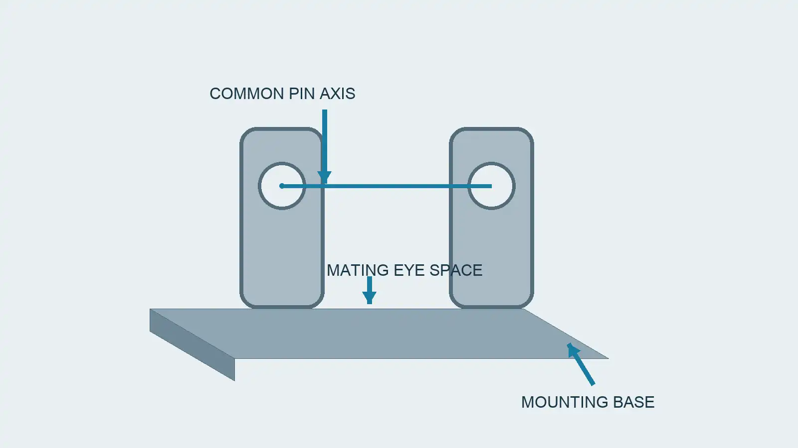
Specify each bore's diameter/finish only as tightly as required by the chosen pin or bushing fit. The slot width and ear-face condition control the mating-eye stack, while the bores control pivot alignment; those are related but not interchangeable requirements. If an assembled bushing will be reamed later, identify the operation and the state at which the bore is accepted. Do not treat a location tolerance measured on a free ear as identical to an in-fixture reading.
Plan machining around ear stiffness and access
A plausible process can rough the outside and slot, preserve support during finishing, establish a stable reference, then machine the pin bores in a coordinated setup where access allows. However, sequence depends on material, ear thickness, bore size, tool reach and fixturing. Long unsupported ears may move under cutting or clamping forces. A temporary bridge, sacrificial stock or dedicated support may be considered during process planning, but each has removal and inspection implications.
If both ears can be reached on one axis without excessive tool deflection, machining from a common setup can reduce transfer error. Where the mounting face, pin axis and adjacent faces require multiple orientations, indexed 3+2 or five-axis access may reduce re-clamping; it does not automatically make the bores coaxial or remove the need for a stable fixture. State the functional requirement on the drawing and let the supplier propose the setup rather than writing “five-axis required” without an engineering reason.
The fork-root fillet matters twice: it can be part of structural design, and it constrains the cutter that creates the slot. Define a minimum radius or approved corner geometry if the mating eye and stress analysis require it. An impossible sharp internal corner should not be inferred from a CAD model. Likewise, specify required edge breaks at pin-hole mouths so burrs do not prevent assembly, but keep them consistent with any bearing or retention surface.
Inspect the free-state bracket and the trial assembly
Measure the bracket after unclamping and any specified heat treatment or finish, if those steps are part of delivery. A free-state check can include mounting-face condition, ear spacing, ear thickness, bore size, bore-axis relationship and bore position relative to the functional mounting datums. A gauge pin through both ears can be a useful assembly screen, but it is not automatically a substitute for the drawing's dimensional requirements. The gauge diameter, insertion condition and whether the bracket is restrained must be agreed.
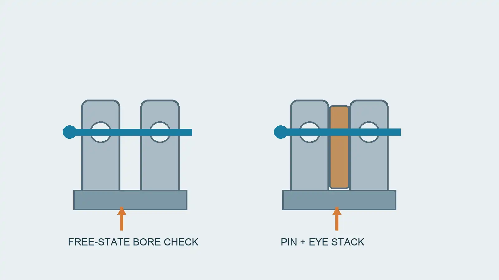
For a finished assembly, also verify that the intended pin, washers and retention hardware install without forcing the ears inward or outward. If the pin only inserts while the bracket is squeezed in a vice, the free-state geometry or assembly stack needs review. Surface finish, coating thickness and any post-finish reaming should be linked to the final fit, not left as disconnected notes.
RFQ information that prevents ambiguous quotes
- Send the revision-controlled model/drawing and identify the mating eye, bushing, pin and retainer by controlled interface dimensions.
- Mark the functional mounting datums, bore-axis relationship and accepted free-state condition using one drawing-standard convention.
- State slot width/clearance, ear thickness, root radius, edge breaks and any finish-affected fits.
- Identify material, heat treatment or coating, and whether inspection is before or after those processes.
- Say whether pin/bushing installation, trial assembly or load testing is in the machining supplier's scope. If not, keep it with the responsible assembler.
This information lets the supplier assess slot access, support and inspection rather than guessing from an attractive CAD model. For multi-face machining inquiries, five-axis machining services is a relevant routing option to discuss, not a substitute for pin-stack and tolerance decisions.
Frequently asked questions
Should both ear holes be drilled in one pass?
Sometimes that is a sensible process route, but it is not a universal requirement. Tool reach, support, bore size, material and final accuracy determine whether drilling, boring, reaming or another sequence is appropriate. The drawing should specify the functional bore relationship, not an unreviewed machining recipe.
Is pin insertion enough to accept a clevis?
No. A pin can enter even when the ear gap, mounting location, bore finish or free-state position is wrong. A defined go/no-go assembly check complements, rather than replaces, dimensional inspection.






