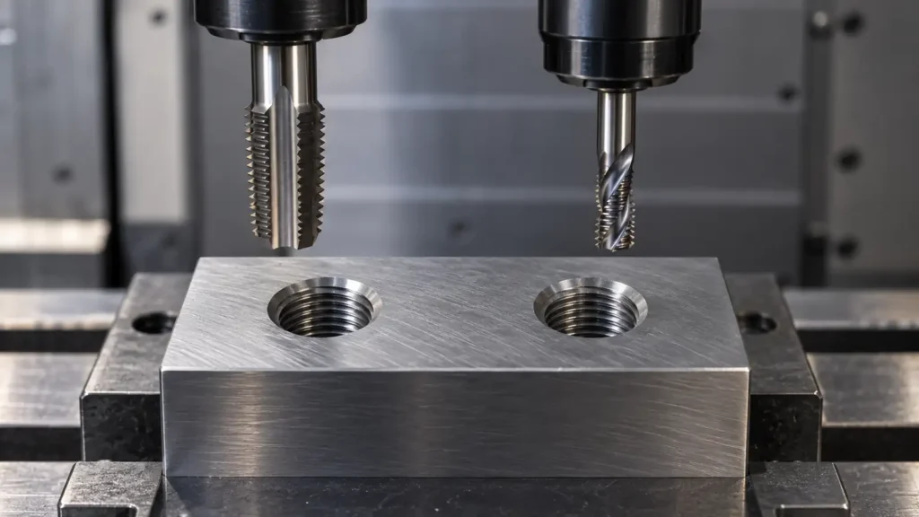
A drawing that calls out an internal thread usually defines the thread, not the cutting method. That is often appropriate: the supplier can choose an efficient process if the finished thread meets the specified fit, location, depth and inspection requirements. But a blind hole close to a floor, a thin wall, a hard-to-machine alloy or an expensive near-finished part can make the process choice consequential. In those cases, discuss tapping and thread milling before the route is locked.
The short answer: tapping is often the simpler route for an accessible, repeatable thread with a suitable tap, machine and chip path. Thread milling can offer diameter adjustment and a different chip and tool-breakage risk profile, but it requires a compatible CNC interpolation strategy, a suitable cutter and a validated cycle. Neither method makes an impossible full-thread depth or an unspecified fit acceptable.
This is a process-selection guide, not a substitute for the applicable thread standard, toolmaker data or a trial cut on the actual material and geometry.
First separate the thread requirement from the process
Specify the finished condition before asking which tool will make it. A useful drawing or RFQ states the thread system and designation, class or tolerance where applicable, required minimum full-thread length, whether the hole is through or blind, entrance-side access, any counterbore or chamfer, and the mating fastener or functional gauge requirement. If the thread sits on a critical face, include its positional relationship to the datum scheme. Do not describe only a nominal drill depth and assume that it proves full usable threads.
The process can remain supplier-selected when a conventional thread meets the functional requirement. Conversely, if assembly clearance, wall thickness, material condition or a repair restriction makes one route unsuitable, identify that constraint. Avoid a drawing note that mandates “thread mill” merely because it sounds higher precision: the acceptance criterion is the produced thread, not a marketing label.
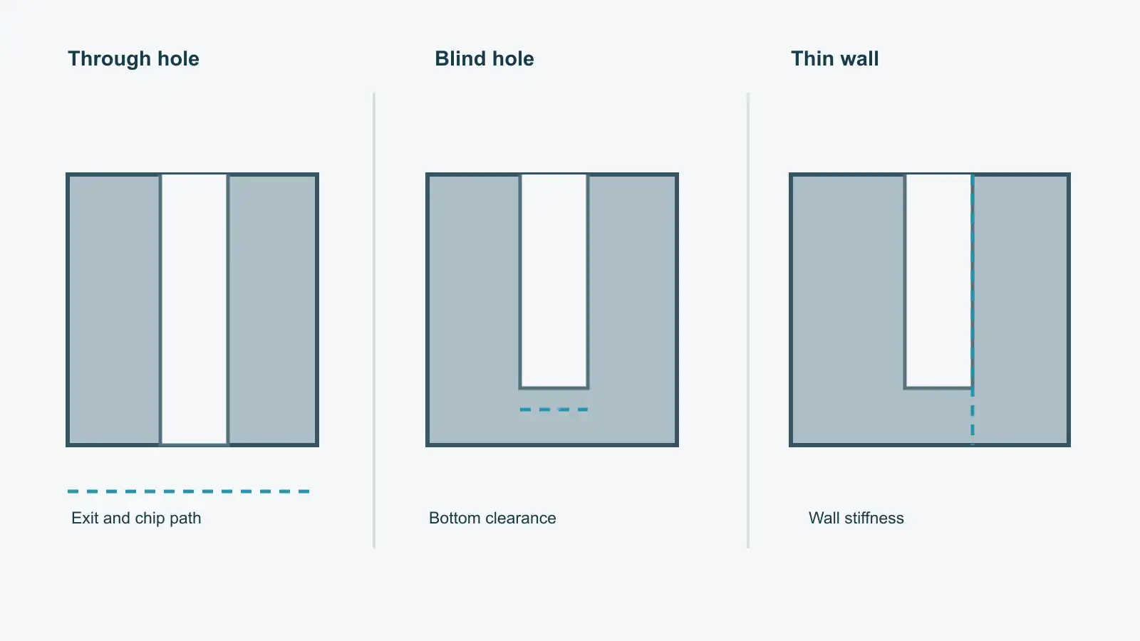
How the two methods differ
A cutting tap advances axially at the thread pitch while its flutes form the entire internal profile. The correct tap geometry, pilot-hole size, holder, lubrication and chip evacuation depend on material and whether chips can leave through the bottom. A thread mill uses a smaller cutter moving on a programmed helical path. It cuts the profile in one or more passes, so the machinist can adjust the programmed radius or tool offset to control the thread's effective size within tool and geometry limits. Tool manufacturers such as EMUGE explicitly identify offset control and chip evacuation as important thread-milling considerations [1].
That distinction does not make thread milling automatically safer or more accurate. A long, slender cutter can deflect; poor entry or exit programming can leave a bad thread; and the tool must physically fit the pilot hole. Tapping can be robust and economical when the hole, material and tooling are well matched. A broken tap can be difficult to remove, especially in a valuable component, but the consequence depends on material, tool size and available salvage methods. Treat “lower risk” as a job-specific calculation, not a universal property.
A practical process-choice matrix
| Part or production condition | Tapping question | Thread-milling question | Decision to validate |
|---|---|---|---|
| Many identical, accessible threads | Is a suitable tap and chip path available? | Does interpolation time add cost without a functional gain? | Compare proven cycle time and scrap exposure. |
| Blind hole with limited bottom space | Is there enough lead and chip clearance for the selected tap? | Can the cutter reach the full-thread zone and exit without damaging the floor? | Draw the full-thread length and total cavity separately. |
| Through hole | Can chips exit safely with the tap style and setup? | Is milling justified by material, size control or tool standardization? | Do not assume through-hole geometry guarantees chip control. |
| Thin wall or low-stiffness boss | Are thrust and torque acceptable for the fixture? | Are radial cutting loads, deflection and burrs controlled? | Prove the resulting thread and wall geometry on representative stock. |
| Difficult or costly workpiece | What is the tap-breakage and recovery consequence? | What is cutter life, access and programming risk? | Evaluate total process risk, not tool price alone. |
| Multiple thread sizes or fit tuning | Is a tap change or size variant acceptable? | Can one suitable cutter cover the specified family, with offsets verified? | Verify each size and tolerance; “one tool” is not automatic. |
This matrix is editorial engineering guidance, not a capability claim for a particular shop. The chosen route needs its own toolmaker application data and production validation.
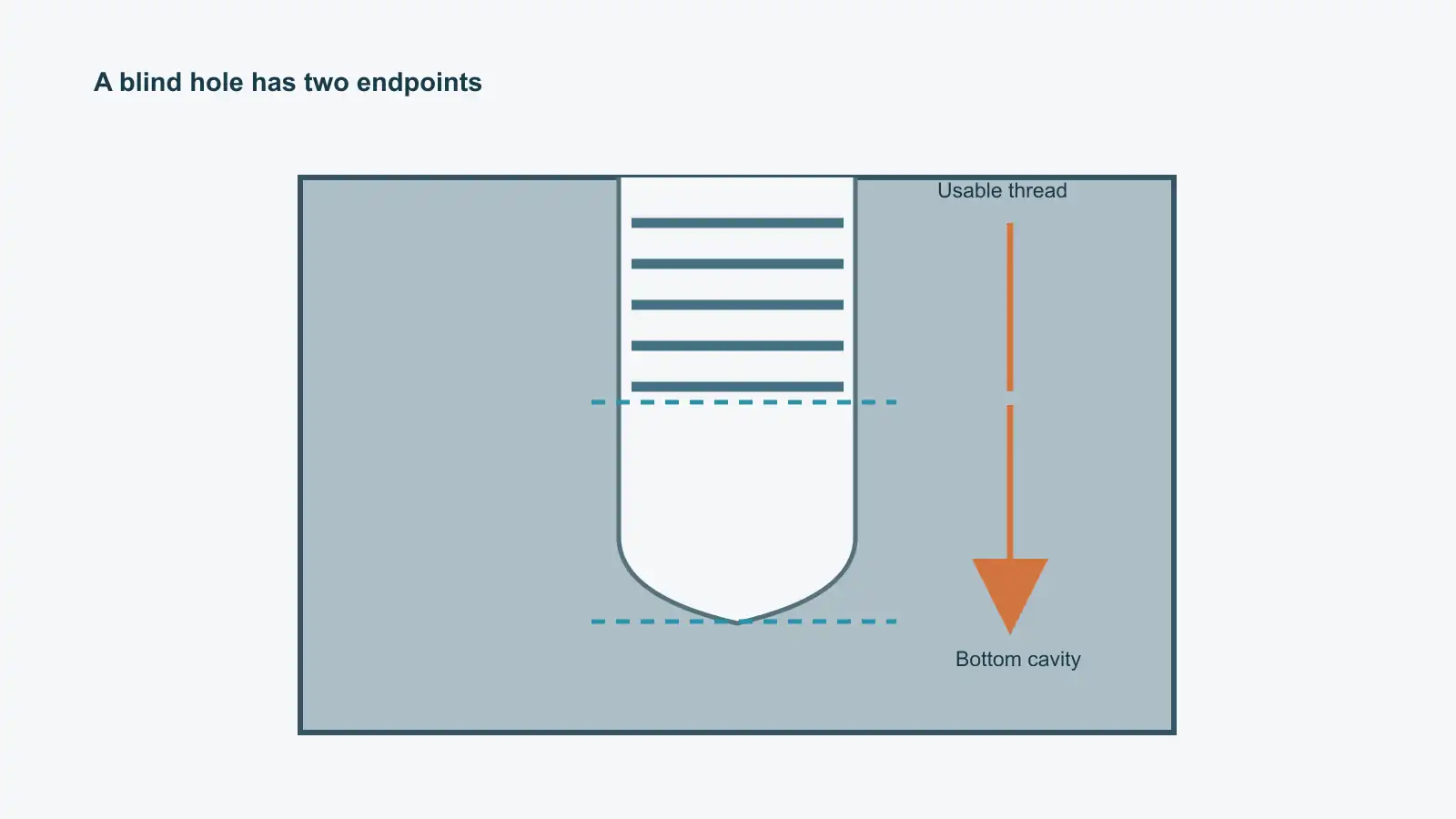
Blind holes: do not confuse bottom clearance with full threads
A blind tapped hole may need room for the tap's chamfer or lead, drill point and chip accumulation. A thread-milled hole has a different clearance problem: the cutter and helix must reach the intended end of the full profile, then disengage without cutting into the floor or wall. Neither route turns the pointed bottom of a drilled hole into usable thread. The toolmaker and machinist should check the actual tap lead or cutter geometry against the required full-thread endpoint.
An RFQ that says “M6 × 1, 12 mm deep” is ambiguous if it does not say whether 12 mm means full threads, drill depth or something else. Use separate dimensions or notes for minimum full-thread length and available hole depth. If engagement is driven by a fastener, provide its nominal length, stack-up and any bottoming restriction. Our separate blind-hole-depth guide addresses this endpoint issue in detail; this article addresses how it affects process choice.
Material and condition can reverse the preference
Workpiece material changes chip formation, tool wear, friction and the consequences of a damaged hole. A gummy alloy, an abrasive casting or a heat-treated steel cannot be reduced to a single “tap or mill” rule. For example, the same nominal steel grade can machine differently before and after hardening, and a hole cut after heat treatment may need a different tool or sequence. Ask the supplier to review the actual grade, condition, hardness range when specified, coolant constraints and whether the thread will be machined before or after coating or heat treatment.
There is also a distinction between cutting taps and forming taps. A forming tap displaces rather than cuts material and has different pilot-hole and material-ductility requirements; it is not interchangeable with a cutting tap. If forming is proposed, qualify it separately. The process review should include burr control at the entrance and exit, possible distortion of a thin boss, and any prohibited lubricant or residue for the application.
For hard-to-machine materials, a thread mill may offer a more manageable cut and adjustable size, but only if the tool is rated for the material, can enter the hole, and the machine/holder maintain the path. EMUGE cautions that grip, chip evacuation and correct feed calculations matter even where milling has advantages [1]. The right conclusion is a tool- and part-specific test, not an unconditional material list.
Fit, location and inspection still decide acceptance
Neither process alone guarantees a thread class. Identify the required thread designation and tolerance system, then agree on the inspection method: suitable GO/NO-GO gauge, mating-part trial where justified, or a documented alternate measurement for special threads. A gauge result evaluates the thread's functional size within the gauge's scope; it does not by itself prove positional accuracy or full-thread depth. Those may need separate checks from the defined datums and depth method.
For a critical threaded interface, inspection should record the stage: before or after heat treatment, coating, anodizing or another finish. A thread that passes before a process may not represent the assembly condition afterward. Define whether coating is allowed inside the thread, whether masking is required, and which party verifies the final state. Do not add an arbitrary oversize allowance without the finish specification and a process trial.
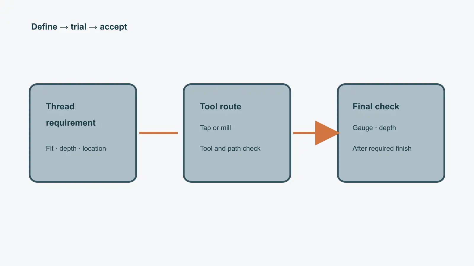
What to send with an RFQ
Send a drawing or model showing the thread callout, minimum usable engagement, blind-hole bottom envelope, entrance-side access and nearby wall or pocket geometry. Add material grade and supply condition, final heat-treatment or finish requirements, mating fastener details where relevant, quantity and inspection requirement. Flag whether a broken tool would make the part non-reworkable. If multiple faces require threaded holes, indicate the datum scheme and assembly direction so the supplier can assess setups and tool access; a five-axis machine does not remove a blocked tool path or change the thread specification.
The supplier can then compare tapping, thread milling and, where appropriate, a separately specified insert or forming process against the same acceptance criteria. For a novel or high-value feature, request a proposed process route and a representative first-article check rather than a promise that one method is universally “best.”
If a removable or reinforced thread is the actual design requirement, see the separate threaded-insert selection guide. For a non-confidential thread drawing review, share the geometry and acceptance requirements through the CNC machining service page or contact form.
Frequently asked questions
Is thread milling always more accurate than tapping?
No. Thread milling permits tool-offset adjustment, but the result still depends on cutter geometry, deflection, path, machine condition and inspection. A correctly selected and controlled tap can also meet the specified thread tolerance.
Does thread milling eliminate broken-tool risk?
No. It changes the likely failure mode and may make recovery easier in some holes, but small cutters can break and a damaged thread may still scrap a part. Compare the consequence on the specific part.
Should I require thread milling on the drawing?
Usually specify the functional thread and restrictions first. Mandate a process only when an engineering reason requires it and the supplier agrees it can be validated.
What is the most important blind-hole note?
Separate minimum full-thread length from total drilled cavity and provide the mating fastener's needed engagement. The tap or thread-mill path must be checked against the actual bottom geometry.
References
- EMUGE-FRANKEN, Three Reasons to Give Thread Milling a Chance, toolmaker guidance on offset control, chip evacuation and programming conditions.
- Sandvik Coromant, Solid Round Tools: Tapping session, toolmaker discussion of blind-hole tapping conditions and chip control.






