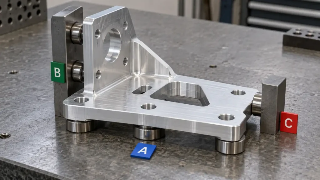
The featured visual is an AI-generated engineering concept, not a customer component, production photograph or inspection record.
A datum scheme should locate the part from functional features and make the tolerance relationships unambiguous. It is not the same as a machinist’s first clamping choice or a CMM program’s convenient alignment. For a multi-face CNC part, the drawing datum reference frame, each setup’s physical locators and the inspection alignment must be intentionally connected so that features cut from different orientations are related to the same design intent.
This guide focuses on choosing and communicating datums. It complements, rather than duplicates, the separate guide to GD&T and CMM inspection for multi-face parts, which covers broader measurement planning.
Choose one governing tolerancing system
ASME Y14.5-2018 (R2024) remains the current ASME dimensioning and tolerancing standard. ASME describes it as establishing the symbols, rules, definitions, requirements and defaults for drawings, digital models and related documents. ISO 5459:2024 is the current published ISO GPS standard specifically addressing datums and datum systems.
These systems share broad engineering purposes, but their definitions, modifiers and default rules should not be blended casually. State the governing standard and edition on the product definition. Interpret every datum symbol and feature control within that system. A supplier should not “translate” an ISO datum callout into an ASME habit—or the reverse—without an approved engineering decision.
A datum is ideal; a datum feature is physical
A datum is a theoretically exact reference such as a plane, axis or point. The datum feature is the real surface or feature on the part used to establish that reference. Manufacturing and inspection contact the imperfect datum feature, then establish a simulated reference according to the governing rules.
That distinction matters because a broad machined base may contain flatness variation, a bore may contain form error, and a pattern of holes may not sit exactly at nominal locations. The datum scheme tells downstream users how those real features establish the reference frame; it does not make the features perfect.
In the familiar A-B-C sequence for three mutually perpendicular planar datum features:
- primary datum feature A removes three degrees of freedom in the idealized model: translation normal to the plane and rotation about two in-plane axes;
- secondary datum feature B removes two remaining degrees of freedom;
- tertiary datum feature C removes the last translation.
This is a useful 3-2-1 visualization, not a substitute for the detailed rules. Datum features of size, datum targets, movable datum features, material-boundary modifiers and non-orthogonal systems require the chosen standard’s definitions.
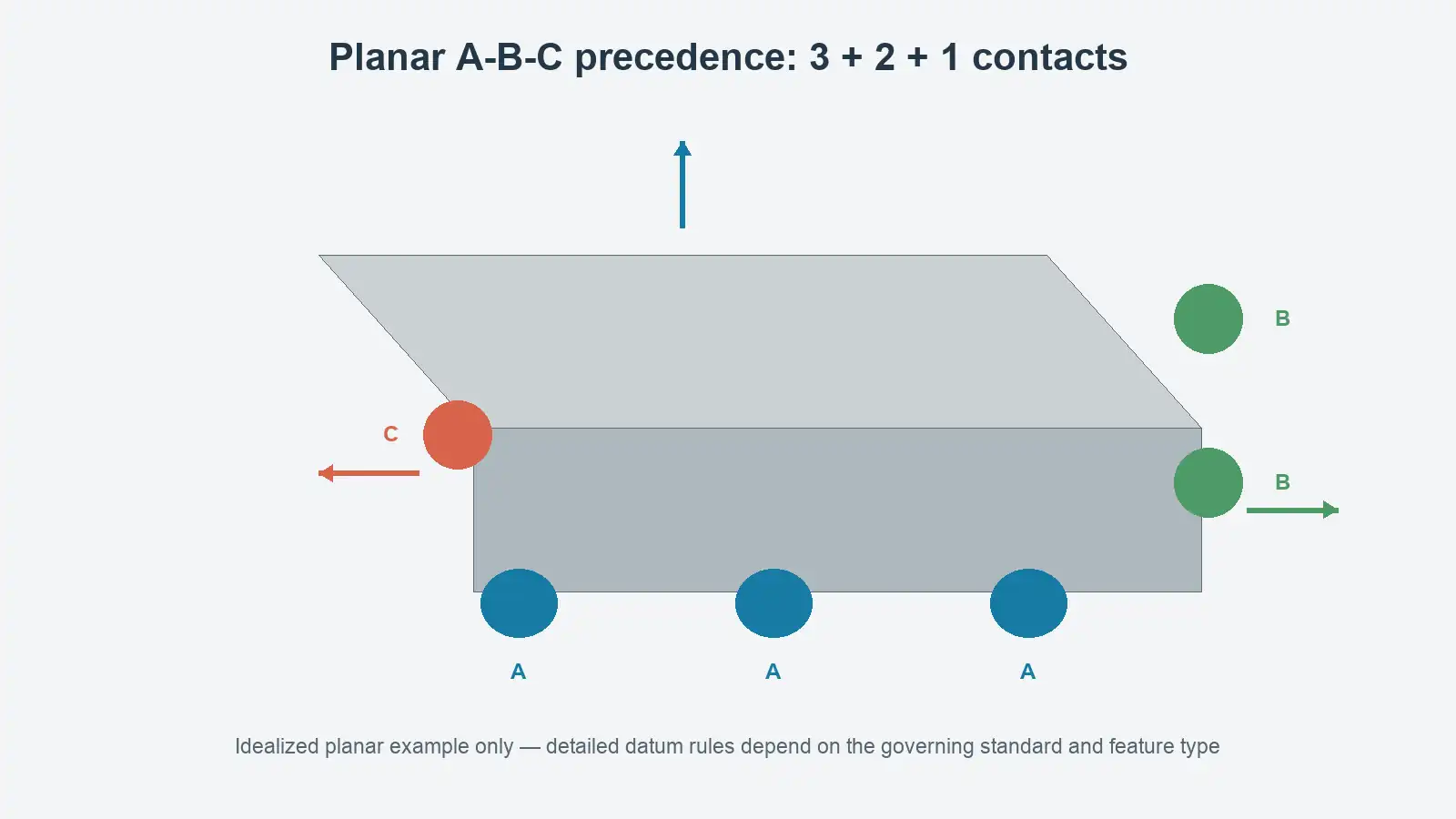
The order A|B|C is precedence, not a statement that all three contacts carry equal importance. The primary feature is established first; the secondary is established while respecting the primary; the tertiary completes the frame while respecting both earlier references.
Select datums from assembly and function
Start with what the part touches, locates, seals, rotates around or aligns to in the product. A stable manufacturing surface is attractive, but convenience alone is not sufficient if it does not represent the functional relationship.
| Candidate datum feature | When it can be useful | Risk to check |
|---|---|---|
| Broad mounting face | Represents assembly seating and provides stable primary support | Burrs, surface texture, coating or distortion may change contact |
| Precision bore | Represents a functional rotational or locating axis | Short length, interrupted surface or access may weaken repeatability |
| Hole pattern | Represents fastener-based assembly location | Pattern clearance and boundary condition must match the selected standard |
| Side face or slot | Controls clocking or lateral location | Narrow contact, draft, edge damage or finish build may make it unstable |
| Datum targets | Useful on irregular, flexible or partially finished surfaces | Target locations and sizes must be fully defined and accessible |
A datum feature should be sufficiently stable, accessible and repeatable for its function. Avoid choosing a small cosmetic edge, a flexible wall or an uncontrolled casting surface merely because it is easy to label. Also avoid using one datum scheme for every requirement when the product has genuinely different functional interfaces; multiple datum reference frames may be necessary, but their relationship must be clear.
Separate design datums from setup locators
The drawing defines the functional datum reference frame. A fixture defines how the part is physically supported and restrained for a particular operation. They may use the same surfaces, but they are not automatically identical.
For example, a finished mounting face may be datum A on the drawing but may not exist during the first roughing operation. The first setup may use stock surfaces or sacrificial features to create A. Later setups can then locate from A and other established features. The process plan needs a traceable transfer from the temporary manufacturing references to the final functional frame.
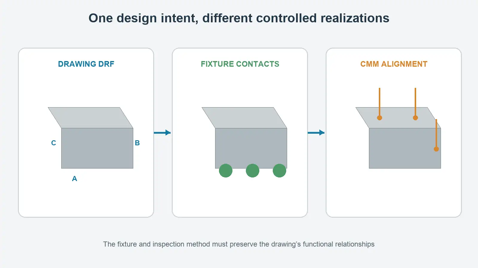
Clamps should hold the part against locators without replacing them. Excess clamp force on a thin section can distort the datum feature; chips or burrs under a support can shift the realized frame; redundant contacts can over-constrain an imperfect part. A robust fixture defines which contacts locate, which support cutting load and which only retain the part.
The inspection system creates another realization. A CMM may probe points on datum features and mathematically establish a simulated datum frame. A hard gauge may physically contact surfaces. Those methods can produce valid but different practical realizations if the drawing, fitting criteria, filters, constraints or contact conditions are not aligned. Inspection planning must follow the product definition rather than reverse-engineer datums from whichever setup is easiest to program.
Plan datum transfer across multiple faces and setups
Multi-face parts often contain holes, pockets and profiles on several orientations. The central risk is not simply the number of setups; it is the relationship lost or re-created when the part moves.
If two critical features must be positioned to each other, referencing both to a common functional datum reference frame can make the intent clear. The manufacturing process then decides whether to cut them in one setup or transfer the frame through qualified locators, probing and offsets. One-setup machining can reduce transfer error, but it does not eliminate thermal drift, tool deflection, rotary-axis error, workholding distortion or inspection uncertainty.
Five-axis machining may improve access and keep more features under one workholding condition, yet it is not a universal datum solution. A simple prismatic part may be more stable and economical in two controlled 3-axis setups. Conversely, a complex bracket may benefit from indexed or simultaneous five-axis access if it reduces long tools or preserves critical feature relationships. The decision should follow geometry, tolerance, fixture access, machine calibration, quantity and inspection strategy—not marketing language.
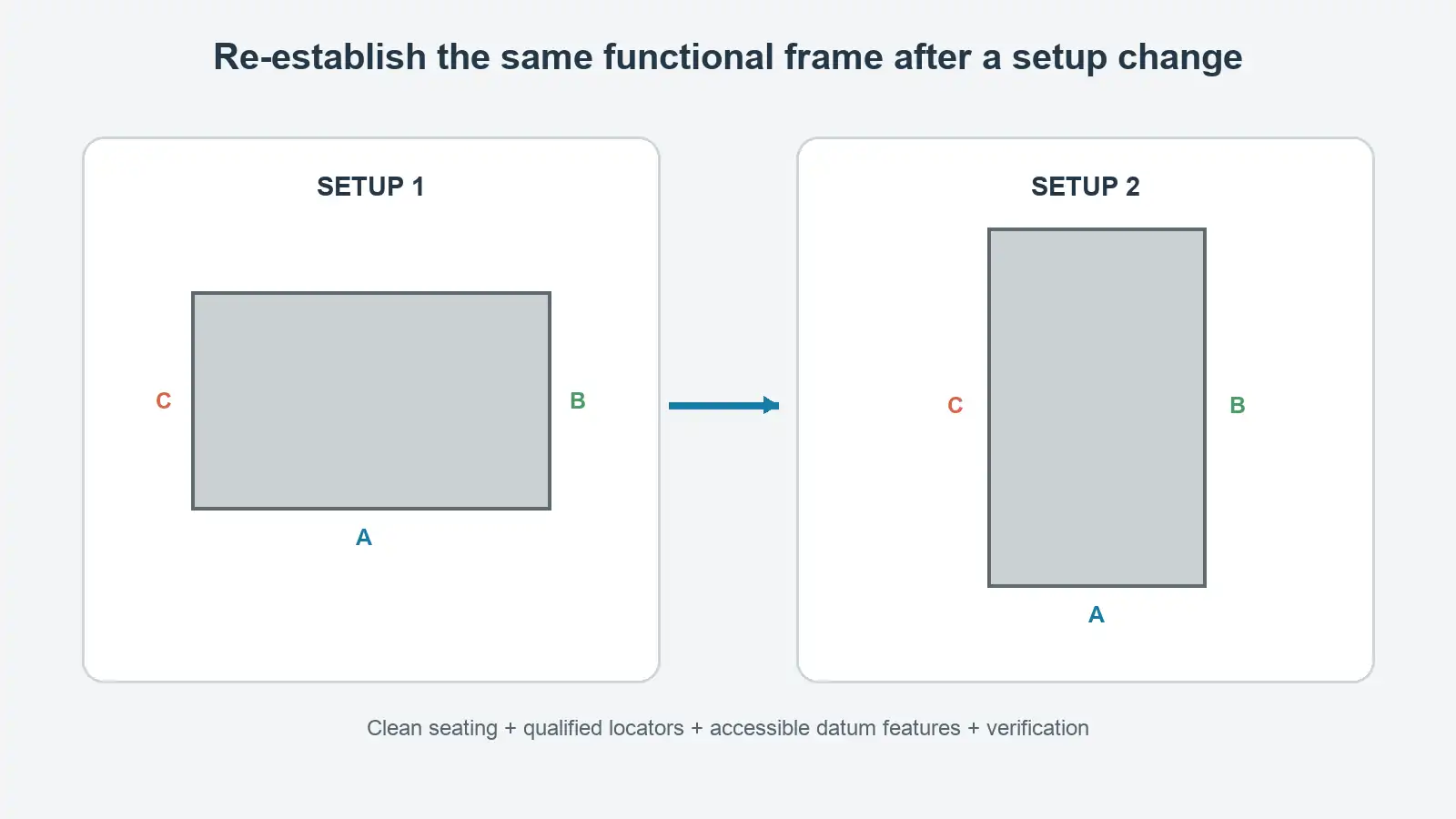
When a setup change is unavoidable, define how the datum frame is re-established:
- create or expose the required datum features in an earlier operation;
- protect those features from burrs, damage and finish buildup;
- use locators with suitable contact geometry and cleanliness controls;
- verify seating rather than assuming clamp force creates it;
- probe or qualify work offsets where appropriate;
- control which features are finished before and after the transfer;
- inspect the relationships that are most sensitive to the transfer.
Make every tolerance measurable from the stated frame
A datum scheme is incomplete if the controlled feature cannot be accessed or the datum cannot be realized with suitable uncertainty. Before release, ask how each critical requirement will be inspected.
For a positional tolerance on a deep cross-hole, can the hole axis be measured over enough length? For a profile around several faces, can the CMM reach the surfaces without an unstable stylus configuration? For a flexible base, will the part be inspected in a free state or restrained as assembled? For a coated datum, is acceptance based on the finished surface or the underlying machined surface?
The drawing should not prescribe a particular CMM alignment unless that method is itself a requirement, but the design must permit a credible verification operator. If the inspection team must ignore the stated datums and create a best-fit alignment to obtain a stable result, the product definition may not be protecting the intended assembly relationship.
Datum targets can help when full-surface contact is not meaningful, but targets must be located, sized and identified. A note that simply says “use three points” does not define a controlled datum system.
Keep 3D models and 2D drawings consistent
Multi-face parts are often supplied as a STEP file plus a PDF drawing, or as an annotated model-based definition. The supplier needs to know which dataset is authoritative and how conflicts are resolved.
ASME Y14.41-2026 is the current ASME standard for digital product definition data practices. In the ISO system, ISO 16792:2021 remains the published edition at this review date, but ISO lists it as scheduled to be replaced by a draft revision. Use the current document required by the contract and recheck status when releasing a controlled dataset.
For either 2D or MBD delivery, include:
- governing GD&T standard and edition;
- units and general tolerance rules;
- clearly associated datum feature symbols and feature controls;
- authoritative model/drawing status and revision;
- saved model views or drawing views that expose multi-face requirements;
- finish, free-state or restraint conditions that affect datum features;
- inspection-reporting requirements and required characteristic identifiers.
Do not let a clean CAD model imply perfect basic relationships while the PDF uses unrelated plus/minus dimensions. The model defines geometry; the tolerancing scheme defines acceptable variation and feature relationships.
What to send for a datum-scheme review
For an efficient RFQ or DFM review, send:
- native or neutral 3D CAD and the controlled drawing or annotated model;
- assembly context showing what the part locates against;
- governing ASME or ISO standard and edition;
- material, stock form and all coating or heat-treatment requirements;
- identified critical interfaces, fits and sealing surfaces;
- proposed datum feature sequence and any alternate frames;
- tolerance requirements tied to those frames;
- free-state, restrained-state or assembly-state inspection conditions;
- expected quantity and repeat-production needs;
- required FAI, CMM report, gauge or traceability output.
The most useful question is not “Can five-axis hold this tolerance?” It is “Does the datum scheme express the functional relationship, can the process establish it through every setup, and can the final part be verified from the same intent?” Review the 5-axis machining service page for multi-face access considerations, then use the contact page to send non-confidential files for review.






