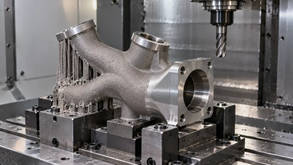
Featured image: conceptual engineering visual, not a JIZAO production photograph or a tested component.
Metal additive manufacturing can create internal passages and shapes that are difficult to make from billet. It does not automatically deliver a ready-to-assemble sealing face, precision bore or thread. Many laser powder bed fusion (LPBF) parts therefore need a planned CNC finishing stage. The important question is not simply whether the printed blank can be clamped. It is whether the blank, drawing and process sequence leave enough accessible material to create and verify the functional interfaces.
This guide addresses an engineer or buyer who already has, or intends to source, a metal AM blank. It is a specification and RFQ guide—not a claim that JIZAO prints parts, has qualified a particular alloy or has measured a customer result. The actual route depends on the supplied blank and an agreed engineering review.
Define two states, not one ambiguous model
Provide the final-state CAD model and a separate representation of the as-built or post-processed blank. The blank definition should identify build orientation, support-contact regions, any sacrificial pads, the expected condition when the machinist receives it, and which surfaces have deliberately retained stock. A nominal final model alone does not show whether a cutter will find sufficient metal at the bore or whether a clamp will crush an unsupported wall.
EOS's metal post-processing overview describes CNC machining as one of several post-processing operations for metal AM parts; support removal, surface treatment and quality control may also be part of the chain. Those operations are not interchangeable. Specify whether stress relief, hot isostatic pressing if applicable, support removal, powder removal or other supplier-controlled steps occur before the finish cut. Do not presume every part needs the same sequence. A change to that sequence can alter accessible datums and final dimensions, so the receiving condition belongs in the purchase documents.
Put finishing stock where function requires it
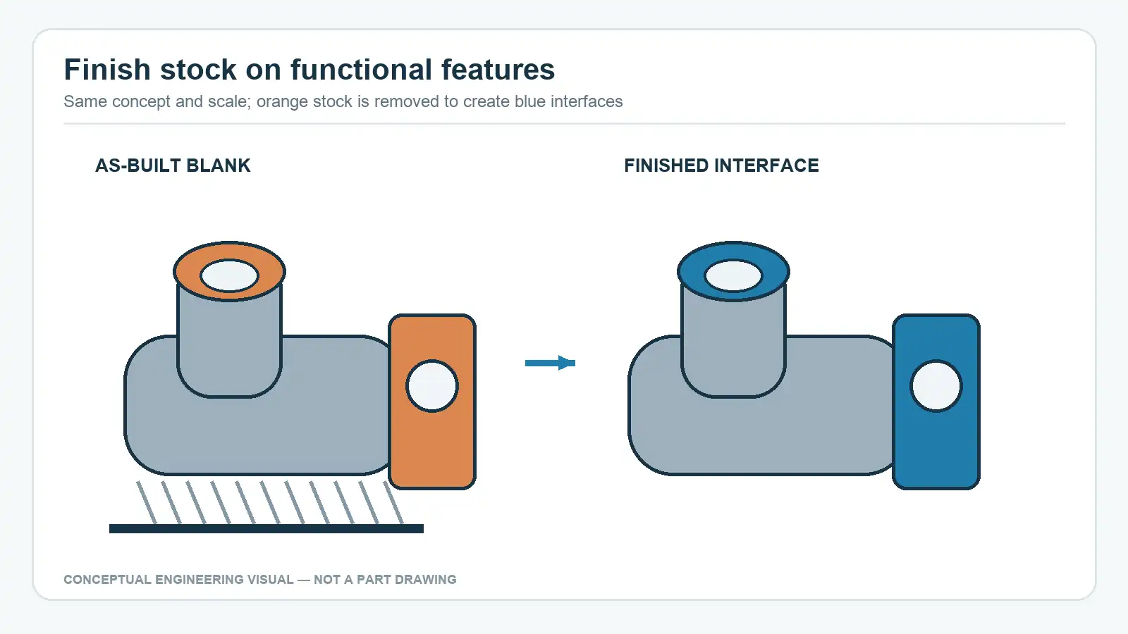
Start with the faces and features that establish assembly fit: sealing lands, mounting pads, locating bores, bearing seats or threaded ports. Mark them as machined in the drawing or model-based definition, and distinguish them from as-built surfaces that may be acceptable as printed. The allowance needs to account for build variation, part orientation, support scars, heat-treatment movement, fixture access and a clean finishing cut. There is no safe universal allowance for every AM geometry or supplier. Ask the AM and machining parties to agree a stock map and inspect a representative blank before finalizing it.
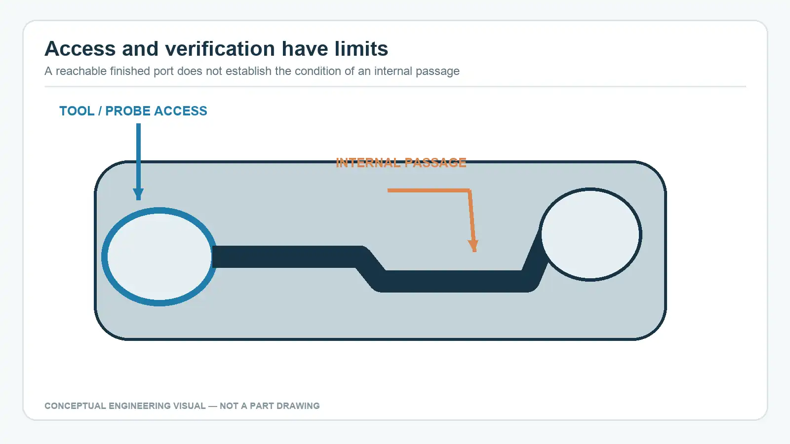
Do not assume a near-net internal channel can be finish-machined merely because it appears in CAD. A cutter or probe may have no line of access. Even when an inlet can be bored, a remote internal wall may remain in its as-built condition. Separate external machined-surface acceptance from internal-channel requirements such as powder removal, flow, cleanliness or non-destructive examination. If internal integrity matters, define a suitable qualified inspection plan with the design authority; surface machining by itself cannot prove that internal AM defects are absent.
An AM blank may also include a thin wall next to a large stock allowance. Cutting the allowance away changes stiffness. Avoid placing a clamp directly over a fragile lattice, passage or unsupported skin. Preserve a sacrificial holding feature where possible, or agree a soft-jaw/nest concept that supports the real load path. The machining supplier should see the blank geometry, not just the finished part.
Separate build references from final datums
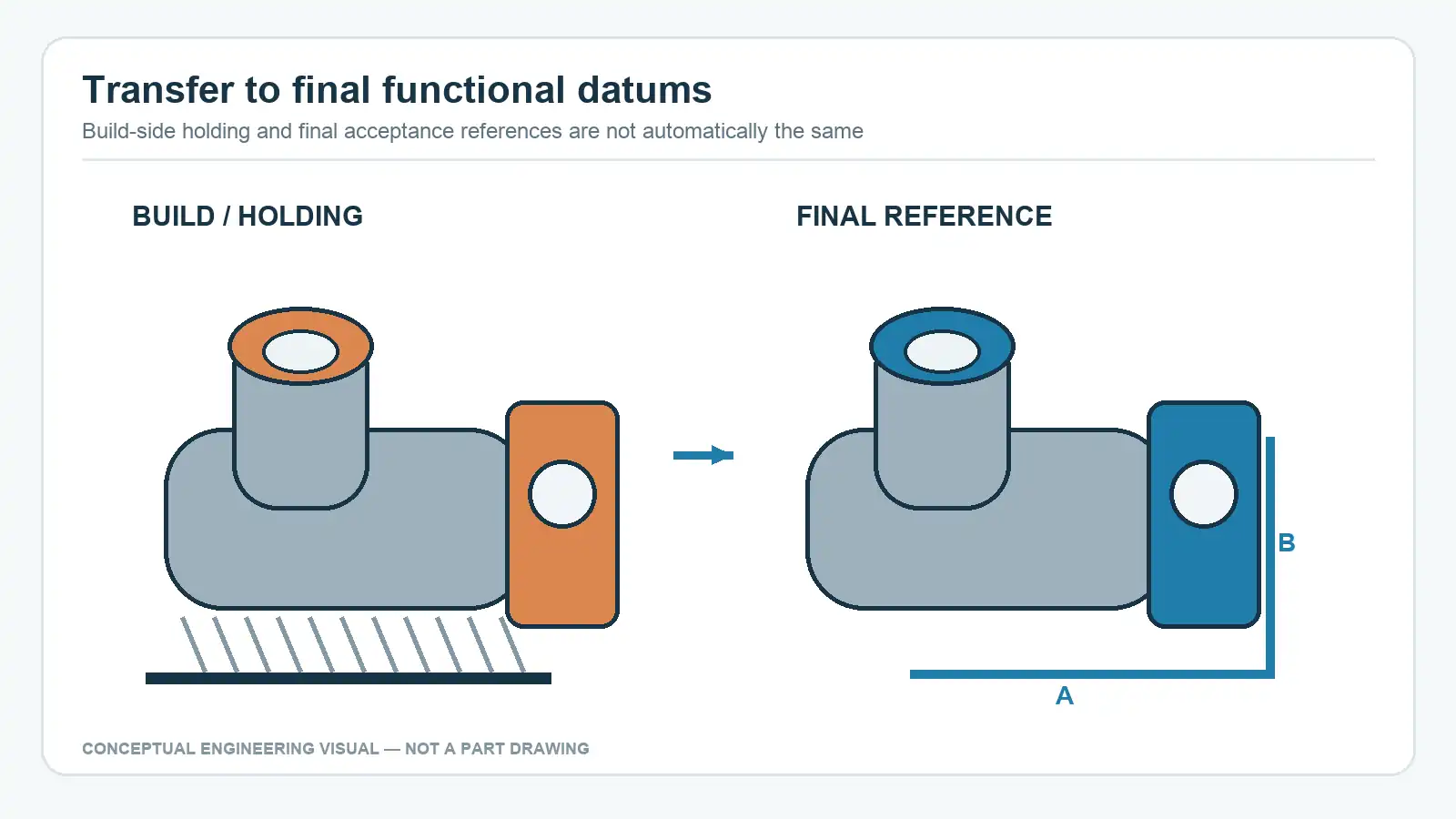
The build plate and support system are useful manufacturing references, but they need not be the functional datum reference frame of the final part. NIST's tolerance-transfer research specifically describes challenges between build and design references in additive manufacturing. Decide which final surfaces establish assembly location, then design a machining sequence that creates accessible primary, secondary and tertiary references without quietly treating the build origin as a finished-part requirement.
An example is a manifold with a mounting face, two locating bores and several angled ports. A first operation could establish a stable mounting face and accessible locating features from the blank's sacrificial holding geometry. Subsequent indexed or multi-axis operations can then relate ports to those finished references. That is a possible planning pattern, not a universal process prescription. If the part is reoriented, document how the reference frame is transferred and where the inspection setup will recover it.
Check complete access, not just tool-tip reach
Angled bosses and curved AM shapes can favor indexed 3+2 or simultaneous five-axis machining, but the axis count is not a quality guarantee. Evaluate the spindle, holder, cutter, workholding and remaining stock through the complete path. A tool that can touch a nominal face may still collide with an adjacent branch or fixture. Tool extension and part support also influence whether the intended finish is realistic. Where a sealing face can be finished in a simpler rigid setup, complexity has no inherent benefit.
If supports are removed before machining, record whether the remaining surfaces are safe to clamp and whether the support-removal operation has damaged a functional interface. If supports remain, verify that removal does not become impossible after another feature is finished. Sequence planning belongs in the joint AM/CNC review, because the geometry and metallurgy may respond differently after each step.
Make the acceptance plan match the final state
List each critical characteristic, its datum reference, whether it is checked before or after surface treatment, and the measurement method. A CMM may verify accessible machined bores and pads; a dedicated gauge may be better for a mating interface. CT, leak, flow or other testing may be required for internal passages, but the method and acceptance level must come from application-specific engineering—not from a generic CNC quote. NIST's AM part-qualification work highlights that internal defects, surfaces and post-processing all complicate AM verification.
Distinguish dimensional conformity from material certification and internal soundness. A dimensionally correct bore does not prove the powder was fully removed or that a pressure boundary is sound. Likewise, a good as-built inspection does not prove a later finish cut left the specified final geometry. Agree who owns each check, its timing and the documentation expected with the shipment.
For a useful RFQ, send the final model and drawing, blank/as-built definition or representative scan, material and build/heat-treatment documentation, planned receiving condition, stock map, functional datums, critical surfaces, quantity, allowable fixture/sacrificial features, and required inspection evidence. Mark any controlled information and use an agreed disclosure route. Ask for explicit exceptions where stock, access or verification is unclear.
Bottom line: design the printed blank and the finish-machining plan together. Functional stock, stable references and measurable final-state requirements matter more than calling the part “near net shape.” For a part-specific manufacturability discussion, review the CNC machining service overview and send the RFQ requirements; the supplier must confirm the actual scope before any capability or tolerance commitment.
FAQ
Can the build plate be the final datum?
Only if the released design intentionally defines that functional reference and it remains available in the final state. Otherwise it is a process reference, not a substitute for drawing datums.
Is one machining allowance suitable for every face?
No. The necessary stock depends on the build, geometry, post-processing, orientation, fixture and required finish. Agree it feature by feature.
Does CNC finishing prove an internal AM channel is sound?
No. Machining verifies or creates accessible external features. Internal cleanliness and integrity require separately specified methods and acceptance criteria.






