A liquid cold plate is not just a milled aluminum pocket with two ports. The drawing must connect the heat-source interface, internal fluid path, closure method, fittings and final inspection state. A supplier may be able to machine the metal body precisely while another party owns bonding, brazing, sealing or thermal qualification. Clarifying that boundary before quotation prevents a dimensionally acceptable part from becoming an untestable assembly.
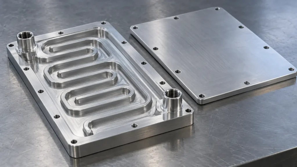
The conceptual featured image shows an open-channel base and a separate cover. It illustrates one possible construction, not a production photograph, proven seal design or JIZAO capability claim.
Start with the thermal and fluid interfaces
Identify where heat enters the plate, where coolant enters and leaves, and what envelope is available. A useful RFQ package includes the heat-source footprint and mounting method, allowable contact-side flatness or profile, thermal interface material (TIM) plan, coolant chemistry and operating temperature, flow range, allowable pressure drop, and the required inlet/outlet fitting standard. If the purchaser has a maximum component temperature or thermal-resistance target, state the test conditions as well as the target; a bare temperature number cannot be evaluated without heat load, coolant conditions and mounting details.
For the machined body, distinguish the device-contact face from the cover-seal land and from any exterior mounting datum. Finish callouts should identify the surface that actually contacts the heat source. Flatness, finish, fastening force and TIM are coupled at the thermal interface; polishing an unrelated visible face will not solve a contact problem. The thermal design and actual heat-transfer performance require analysis or testing by the responsible engineering team, not an inference from a CNC image. Boyd's thermal-interface guidance explains why contact resistance depends on the joined surfaces and assembly conditions.
Select a channel route that can be machined, closed and cleaned
Machined channels under a separate cover are one construction option; embedded-tube cold plates are another. Wakefield Thermal's cold-plate overview describes these alternatives. A routed channel must be assessed together with the cover and the method used to close it. In a conventional end-milled channel, cutter diameter limits inside corners, channel floor geometry and access near ports. The cover needs a continuous joining or sealing land. Joining can change distortion and the finished contact-face condition, so the purchaser should state which dimensions are controlled before closure and which are accepted afterward.
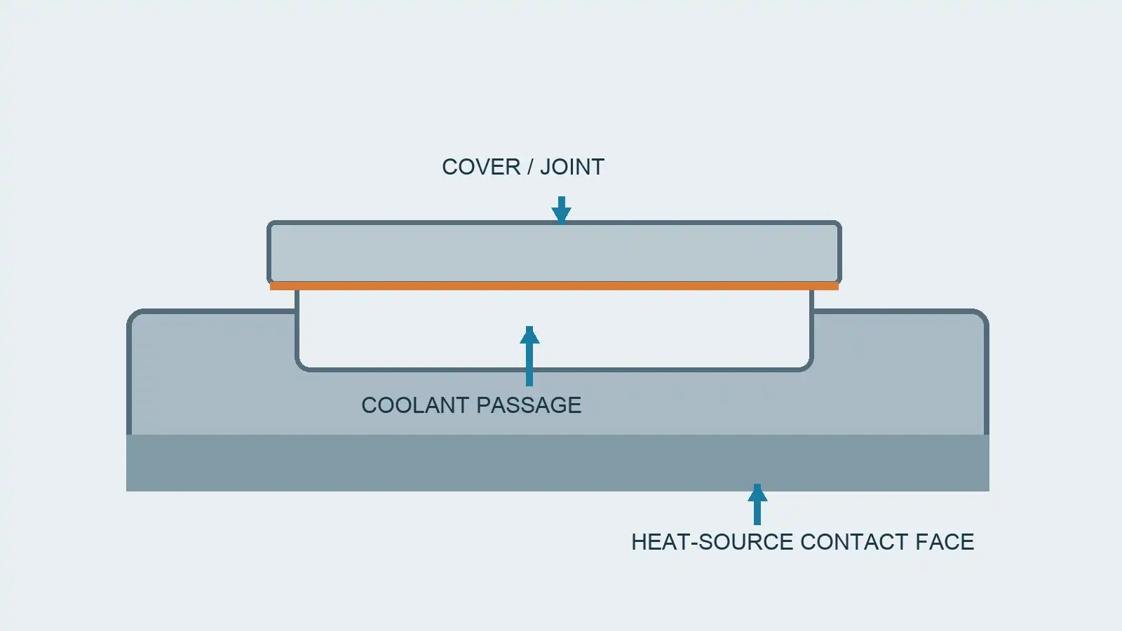
At bends and intersections, avoid blindly adding narrow islands or inaccessible pockets that complicate cutter access and debris removal. State whether passages need deburring, flushing or a specified cleanliness verification. A visible open channel may be easy to inspect before closure but inaccessible afterward. Record the inspection hold point if the channel floor, edge breaks or cleanliness must be witnessed before the cover is attached.
Flow path choice affects heat pickup and pressure loss, but the drawing alone does not prove a required thermal result. Ask the thermal engineer to evaluate hydraulic and thermal behavior for the specified coolant, flow and load; ask the machining supplier to review the geometry and accessible surfaces. A five-axis setup can be useful for angled ports or multi-face features when it reduces reorientation, but it does not replace flow analysis, sealing design or final tests.
Treat ports and closure as a separate specification
An inlet drawing should tell a machinist whether the port is a threaded fitting interface, a boss for a welded connector, or an opening finished by a later assembly step. Include thread or fitting designation, sealing surface, port orientation, minimum wall and access for a tool or connector. Do not assume that a threaded hole is itself a leak-tight fluid interface. If ports intersect milled channels, check the remaining material and the burr-removal route.
For a removable cover with an elastomer seal, provide the seal compound, coolant compatibility, temperature/pressure envelope and gland definition approved by the sealing engineer. Parker's O-Ring Handbook addresses face-seal geometry and application-dependent material and gland selection. Its catalog dimensions are not a universal cold-plate recipe. If the cover is brazed, welded or bonded instead, specify the process owner, joint preparation, finish sequence and acceptance criteria; do not leave an unspecified “seal as required” note to the CNC shop.
Define what is measured, at which state
Separate three questions in the purchase order. First, is the machined body geometrically correct? Check port location, channel boundaries where accessible, contact face and cover land against the intended datums. Second, is the closed assembly leak-tight under a defined medium, pressure, duration and acceptance threshold? Third, does the assembly meet the flow or thermal requirement at the stated operating conditions? These are different tests; passing one does not imply passing the others.
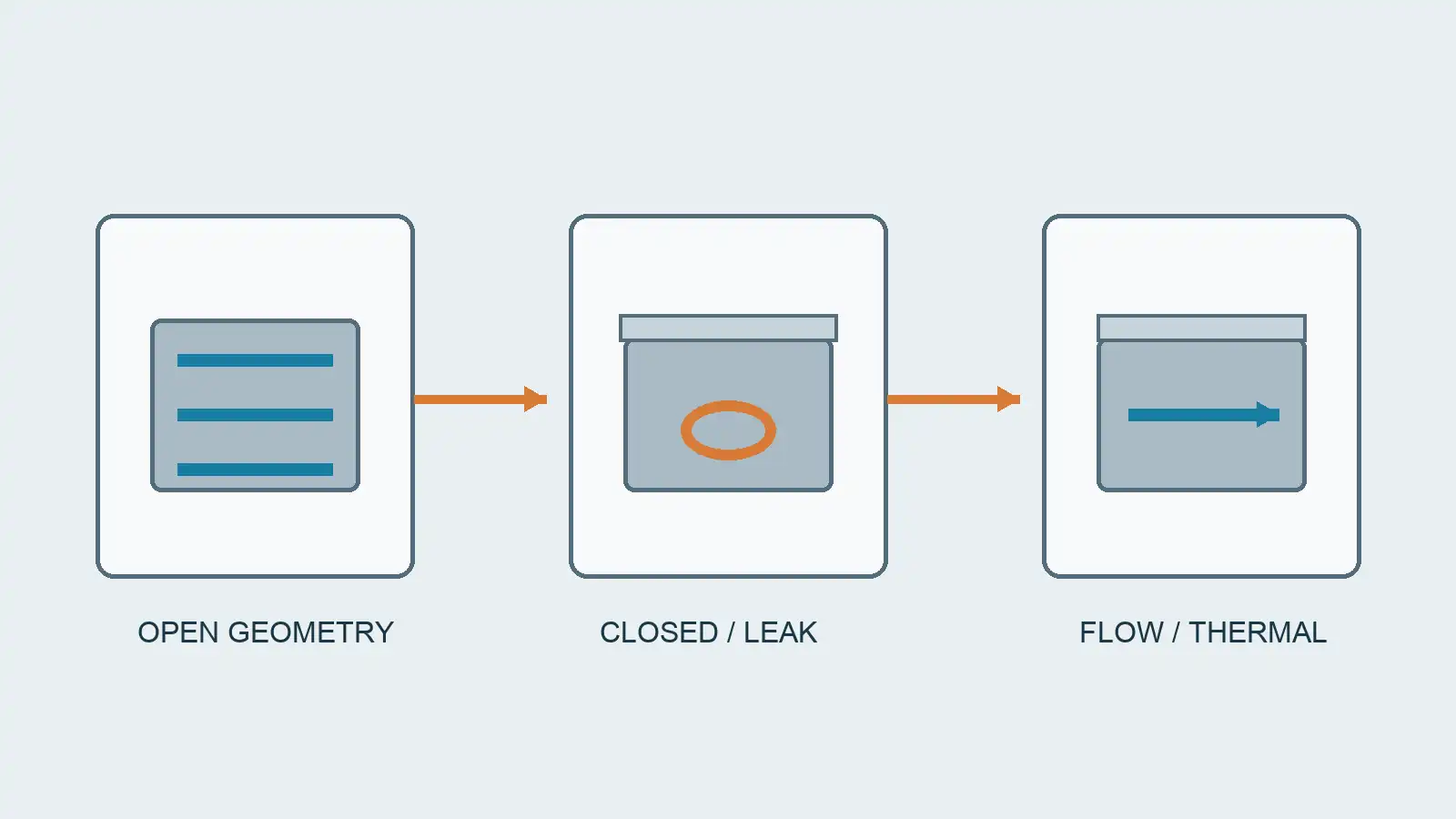
If a face is skimmed after joining, its post-process dimension must be called out. If a coating or surface treatment is planned, indicate whether it applies inside the fluid passage, on the contact face and on seal lands. These decisions can change the final dimension, fluid compatibility or contact resistance. Agree on the order of operations and the final inspection state rather than applying a blanket tolerance to every intermediate component.
RFQ checklist for an actionable cold-plate drawing
- Provide a 3D model and controlled 2D drawing with material, units, revision and datum references.
- Show the heat-source footprint, contact-face requirement, mounting stack and thermal-interface assumptions.
- Define coolant, flow/pressure conditions, inlet/outlet connection, channel boundary and cleanliness requirement.
- Identify cover construction and who owns joining, sealing, subsequent facing and final assembly.
- Separate pre-closure dimensional checks from post-closure leak, flow and thermal tests, including their acceptance conditions and responsible party.
- Flag any features on adjacent faces where indexed or simultaneous multi-axis machining may help, without prescribing five-axis machining as a performance guarantee.
An RFQ with these boundaries lets a machining supplier quote the features it can actually control and lets the system integrator own the seal and thermal evidence. For a machining-focused inquiry, see CNC machining services and provide the drawing, model and acceptance plan for engineering review.
Frequently asked questions
Can a CNC-machined plate be accepted before its cover is attached?
The open body can be accepted for specified geometry and cleanliness. It cannot establish the leak integrity or thermal performance of a future closed assembly. Specify the intermediate hold point and the final acceptance separately.
Does a serpentine channel always cool better?
No. The answer depends on heat-source position, channel geometry, coolant, flow, pressure drop and the rest of the loop. A route should be selected through application-specific thermal and hydraulic evaluation, not its visual complexity.






