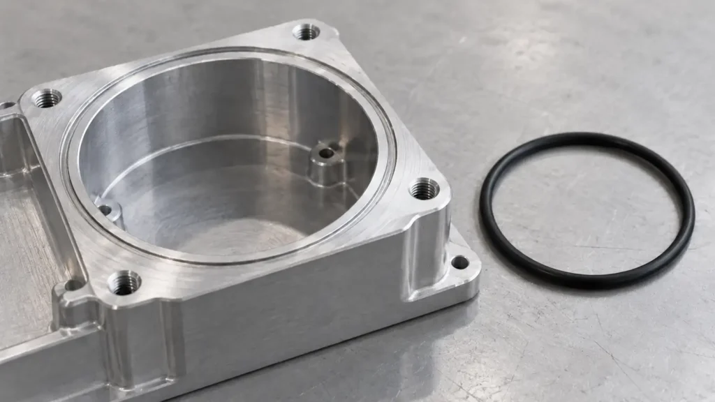
Design the seal as an assembly, not as a slot cut into one part. First identify whether the O-ring seals a stationary face, a stationary radial gap, or a moving interface. Then define the fluid, temperature, pressure direction and range, motion, leakage target, and expected life. Select a specific O-ring size and compound with a seal supplier; calculate the gland around the installed ring and the closed mating parts. Check the worst-case squeeze, available groove volume, stretch or outside-diameter interference, extrusion gap, assembly path, and verification method before releasing the CNC housing drawing. Trelleborg's design guide treats these as linked decisions (Section B.2, pp. 48–59), not one universal groove formula.
1. Classify the seal before opening a gland table
The same O-ring cross-section can sit in very different hardware. The direction of compression, the surface that moves, and the clearance exposed to pressure change the design calculation.
| Arrangement | Where compression occurs | What changes the design |
|---|---|---|
| Static face seal | Axially between two closed faces | Flange closure, pressure direction, face form and fastener load; groove may retain the ring during assembly. |
| Static radial seal | Radially between a piston or rod and a bore/housing | Bore and shaft diameters, concentricity, ring stretch or OD interference, and the pressure-side extrusion clearance. |
| Dynamic radial gland | Radially, with a sliding or rotating mating surface | Friction, wear, lubrication, side load, velocity and heat in addition to basic sealing geometry. |
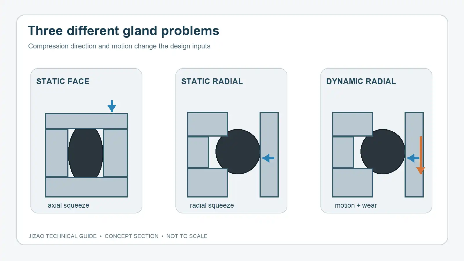
Do not transfer a static face-seal depth into a moving rod gland because both use the word groove. Trelleborg's O-Ring Calculator asks for application type and applies different limits for static/dynamic radial and internal/external pressure axial cases. Its June 2024 catalog also says it does not recommend O-rings as a general rotary-shaft seal; that case needs specialist review (Section B.2, p. 52). A face seal that opens repeatedly, a high-pressure hydraulic gland, gas/vacuum service, or chemically aggressive media likewise deserves seal-supplier involvement rather than a copied catalog row.
2. Fix the operating envelope and the actual seal
Specify the medium, concentration if relevant, continuous and peak temperatures, pressure and pressure reversals, motion type and speed, assembly frequency, lubricant, and allowable leakage or test criterion. These variables determine material compatibility and whether swelling, thermal expansion, compression set, extrusion, friction or wear becomes the limiting risk. Trelleborg explicitly treats temperature, pressure and media as interacting selection parameters (Section B.2.6, p. 54). A rubber family alone is not a compound specification.
Choose the ring's nominal inside diameter and cross-section from a controlled size system, plus the compound and hardness approved for the service. ISO 3601-1:2012 defines O-ring sizes, tolerances and designation codes and remains current with an amendment. Hardness changes assembly force and extrusion resistance, but “harder” is not automatically “better”: the compound's low-temperature response, media resistance and ability to conform to the surface matter too. Record the supplier part number or material specification, not simply “black O-ring.”
The product engineer or seal supplier owns that selection. A CNC shop can review the metal groove's machinability and measurability; it cannot infer seal compatibility or a leakage guarantee from a STEP model.
3. Calculate squeeze in the closed assembly
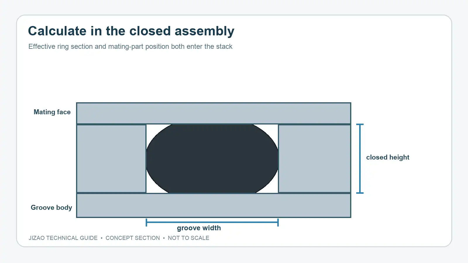
Squeeze is the reduction of effective O-ring cross-section along the compression direction. For a simple rectangular gland, an initial geometry check is:
nominal squeeze fraction = (effective installed cross-section − closed gland height) ÷ effective installed cross-section.
For a face seal, closed gland height depends on the groove depth and the actual flange separation after closure. For a radial seal, it is the assembled radial space from groove bottom to mating bore or shaft; the bore or shaft tolerance belongs in the calculation. The effective cross-section may change when the ring is stretched, so it is not always the catalog's free-state cross-section. Trelleborg explains stretch-induced cross-section reduction in Section B.2.3 (p. 51) and distinguishes approximate initial-compression ranges by application in Section B.2.4 (pp. 52–53). Those ranges are application guidance, not a single target for every gland.
As arithmetic only, if an installed ring section were 3.0 mm and the closed gland height were 2.4 mm, the nominal squeeze would be 20%. That does not establish a suitable design: the ring section and closed height both have tolerances, the section may thin under stretch, and thermal or fluid exposure can change the elastomer. Recalculate minimum and maximum squeeze using actual ring tolerances, metal dimensions, coating state and mating-part variation, then compare the results with the selected seal supplier's guidance. Do not place the illustrative 3.0/2.4 mm numbers on a production drawing.
4. Check width, fill, fit and pressure clearance together
Groove width gives the ring room to deform; groove depth helps set squeeze. A nominal squeeze check can pass while a narrow groove has too little free volume after temperature rise or fluid swell. Conversely, a very wide groove can leave the ring poorly located during pressure reversals or assembly. For radial sealing, Trelleborg's 2024 guide recommends limiting groove fill to 85% in its Section B.2.5 (p. 54) to allow for thermal expansion, swell and tolerances. Treat that as that manufacturer's radial-seal guidance, not a universal face, dynamic, encapsulated or special-material rule. If a back-up ring is used, its thickness also changes required groove width (Section B.2.7, p. 59).
Check how the ring is retained before assembly. A piston groove generally installs the ring with inside-diameter stretch; a rod housing relies on controlled outside-diameter interference. Axial face designs must account for whether pressure comes from inside or outside so that the unpressurized ring is located against the appropriate groove wall. Trelleborg gives different sizing relationships for these cases in Section B.2.2–B.2.3 (pp. 49–51). Use its equations and limits only for their stated geometry and material conditions, especially where a very small or large ring changes the fit problem.
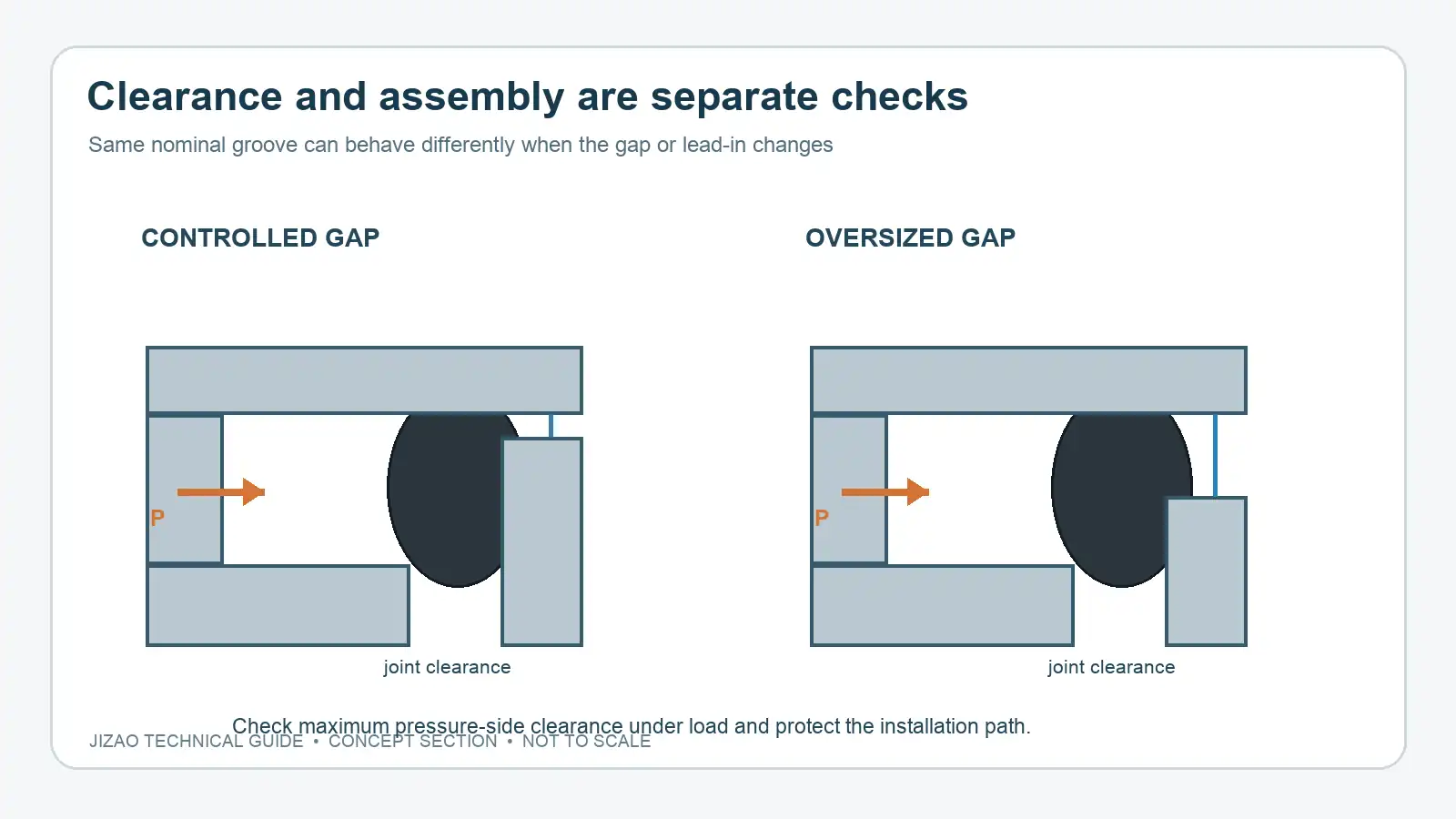
The extrusion gap is the clearance into which the ring can be driven under differential pressure. Evaluate the largest gap after tolerances, eccentricity, deflection, temperature and pressure-induced movement, not just the nominal CAD section. Pressure, ring cross-section, hardness and material change the permissible gap; a back-up ring may be needed for a qualified design. Trelleborg's Section B.2.7 (pp. 55–56) includes conditional clearance tables and warns that too much gap can damage the seal. Do not quote the table without its pressure, section, hardness and concentricity assumptions.
5. Design the metal surfaces and the installation route
The sealing land, groove floor, groove flanks and lead-in are different surfaces. A low average roughness number alone does not rule out scratches, pits, spiral tool marks, burrs or waviness. Dynamic mating surfaces have different demands from static faces. Trelleborg's Section B.2.7 (pp. 55–57, especially Table 19) treats surface condition and lead-in geometry by location and duty; its 2024 table also uses some older surface-parameter references, so a new drawing should express the required texture in its selected, current drawing-standard system rather than copying symbols blindly.
Plan the path the O-ring takes into the gland. Round or chamfer edges it crosses, deburr transverse bores, protect threads and splines, clean chips and abrasive particles, and use only a lubricant compatible with the chosen elastomer and fluid. Do not stretch or twist a ring simply to make an awkward assembly possible. Those measures follow Trelleborg Section B.2.1–B.2.2 (pp. 48–49) and should be translated into part-specific drawing and assembly instructions.
For a CNC-machined housing, the drawing should name the finished groove dimensions and tolerances, datum relationship to the mating bore or face, pressure side, surface and edge requirements, coating/masking state, and the condition in which each characteristic is accepted. A groove can be machined to its nominal size yet lose squeeze when the mating flange bows or a coating changes the finished depth. Our companion guide, CNC Machining O-Ring Grooves: Gland Geometry, Surface Texture and Inspection, focuses on translating an approved seal design into machining and inspection requirements.
6. Validate the assembly, not only the isolated groove
Review a worst-case stack in both directions: minimum effective ring section with maximum closed height tests loss of contact; maximum effective section with minimum height tests over-compression and assembly force. Include maximum fill after expected swell and temperature, maximum extrusion clearance at pressure, and installation damage. A tolerance spreadsheet or supplier calculator is useful only when inputs describe the actual compound and assembled hardware. ISO 3601-2:2025 is the current general-application housing-dimension standard; it explicitly expects special applications to be agreed between O-ring manufacturer and user. Trelleborg's June 2024 catalog predates that edition, so do not describe its tables as 2025 standard dimensions.
Set a verification plan around the failure risk. Inspect ring identity and condition, groove width/depth and mating geometry in the specified finish state, critical edge and texture condition, and assembly method. Then define the leak or functional test by medium, pressure, temperature, duration, boundary, acceptance criterion and whether the part is tested before or after assembly and aging. A leak test on one prototype does not prove life under thermal cycles or repeated motion; qualification should represent the intended service. No AI image or generic catalog calculation is evidence of a tested JIZAO seal.
Engineering RFQ checklist for a CNC metal housing
Send the following as one controlled package to the seal-system owner and machining supplier:
- Service envelope: fluid, peak/continuous temperature and pressure, pressure direction or reversal, motion, duty cycle, leakage target and test method.
- Seal definition: exact O-ring size system and designation, compound, hardness, supplier part number, and any back-up ring or lubricant.
- Assembly geometry: 3D model plus drawing of both mating parts, closed gap/closure method, groove width/depth and diameters, datums, clearance path and installation access.
- Finished surface: which lands, floor and flanks seal; texture and defect limits; lead-in, burr and cleaning rules; coating or masking and final measurement state.
- Verification ownership: supplier-approved gland calculation and revision, worst-case tolerance stack, groove and mating-part inspection, assembly instructions, leak/functional qualification, and who signs off each result.
If the seal supplier has not approved the compound and gland, request a design review before asking a CNC shop to quote a supposed “standard groove.” For a metal housing or flange drawing, JIZAO can review the machining and inspection implications of the approved design through a drawing/RFQ discussion; the seal-system owner must confirm service suitability and validation.
Sources and applicability
- Trelleborg, O-Rings & Back-up Rings, edition June 2024, Section B.2, pp. 48–59. Original manufacturer PDF inspected; its recommendations apply within the stated elastomeric O-ring and application conditions, not automatically to special materials or the later ISO edition.
- Trelleborg O-Ring Calculator, application-type and material/hardness inputs; access to the calculation itself requires a registered account.
- ISO 3601-1:2012, current ISO page for O-ring sizes/tolerances (with Amendment 1:2019); ISO 3601-2:2025, current general-application housing-dimension standard. Public abstracts/status were checked; full paid standard tables were not represented as reviewed.






