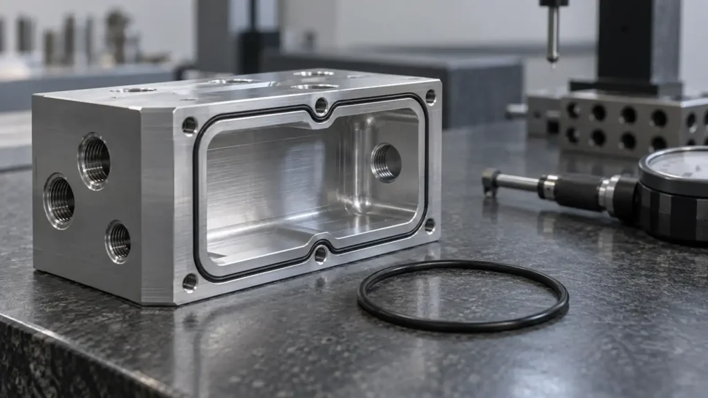
An O-ring groove does not seal because a circular slot exists. It seals when the selected O-ring, gland geometry, mating surface, pressure direction, material and operating conditions work as a system. For a CNC supplier, that means the drawing must define more than a nominal groove width and depth.
This guide explains what a designer or buyer should specify before quoting a machined O-ring groove, how machining choices affect the sealing interface, and how to build an inspection plan without inventing a universal groove size or roughness value.
Quick answer
Choose the O-ring and sealing arrangement first. Then define the governing standard or seal-manufacturer calculation, groove width and depth, corner and edge conditions, datum relationship, surface-texture requirement, coating condition and inspection evidence. Static face seals, radial piston or rod seals, vacuum seals and dynamic seals do not share one universal gland design.
Start with the seal application
A useful RFQ identifies whether the groove is for a static face seal, a radial internal or external seal, a reciprocating or rotary interface, vacuum service, or another special condition. That classification changes which surfaces compress the O-ring, where pressure acts and whether friction, lubrication, extrusion or permeation dominates the risk.
ISO 3601-1:2012 defines O-ring inside diameters, cross-sections, tolerances and designation codes. ISO 3601-2:2025 addresses housing dimensions for general industrial applications and explicitly recognizes that special applications may need agreement between the manufacturer and user. A seal-manufacturer handbook can add material- and application-specific guidance. None of these sources means a CNC shop should choose the seal system without the designer's service data.
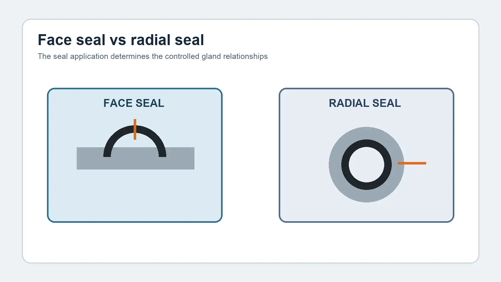
Face seals and radial seals control different relationships
In a face seal, groove depth and the closing gap largely establish compression while width provides space for the elastomer to deform. The land, groove bottom, mating face and pressure side all matter. In a radial arrangement, the bore or shaft diameter participates directly in gland geometry; concentricity, roundness and surface direction may be as important as the groove itself.
Do not copy a gland table until the O-ring series, cross-section, compound, temperature range, pressure, movement and mating hardware are known. Published tables are design inputs under stated conditions, not a substitute for application review.
What belongs on the drawing
The drawing should communicate the functional boundary clearly:
- O-ring size or designation and the governing design source;
- seal type and pressure side when orientation matters;
- finished groove width, depth and diameters or profile;
- relationship to functional datums and mating features;
- edge-break or lead-in requirements that protect the seal during assembly;
- permitted corner radii where the standard or seal design allows them;
- surface-texture requirement and measurement direction or method when critical;
- coating, plating or anodizing condition for the controlled dimensions;
- burr, scratch, dent and tool-mark acceptance for sealing surfaces;
- inspection report or sampling requirement.
Avoid notes such as “O-ring groove per standard” with no part number, series, application class or edition. They force the supplier to infer the design basis and make quoting less reliable.
Groove dimensions interact, so tolerance them by function
Width, depth, mating clearance and O-ring cross-section combine to determine squeeze and available gland volume. Tightening one dimension does not compensate automatically for ambiguity in the others. A groove may meet width and depth size limits yet still fail function if its position, mating-face form, edge damage or coating buildup is uncontrolled.
Define the condition in which acceptance applies. If anodizing or plating covers the groove, the finish can change width, depth, edge condition and texture. A pre-finish machining dimension and a post-finish functional requirement are not interchangeable. State which surfaces are coated or masked and which dimensions are verified after processing.
Surface texture is more than one Ra number
The sealing interface can be affected by roughness, waviness, scratches, burrs and lay direction. Ra alone is an average parameter; it does not describe every peak, valley or isolated defect. Use the current ISO 21920 framework if the drawing follows ISO GPS, and keep the symbol system consistent with the drawing standard.
The required texture depends on seal material, motion, pressure, lubrication and leakage target. A dynamic seal may need a different surface and lay strategy from a static face seal. An extremely low roughness target can add finishing and inspection cost without solving a poorly selected gland geometry.
For RFQ purposes, identify the surfaces that need texture control and the condition under which they are measured. If a stylus cannot access the groove reliably, agree on an alternative method or a representative process-control feature before production.
Plan machining and inspection together
Groove production may use circular interpolation, turning, form tools or special cutters. Tool access, cutter diameter, reach, chip evacuation and entry strategy influence corner geometry and marks. The most economical method depends on the part, not on the word “groove.”
Inspection should follow the characteristic:
- width may be checked with suitable contact or optical methods;
- depth must be related to the correct adjacent surface and datum condition;
- diameters or profile may require optical, CMM or dedicated gauging;
- surface texture needs an accessible measurement path and stated evaluation conditions;
- edge condition and scratches often need defined visual acceptance criteria.
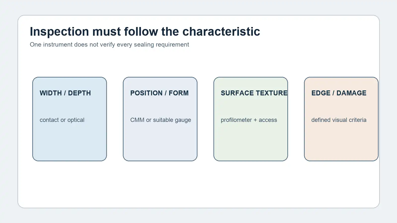
A CMM can evaluate geometry and position, but it does not automatically verify texture or every narrow corner. A profilometer can measure texture only where the stylus and evaluation length are appropriate. The drawing, process and measurement method therefore need to agree.
Common RFQ failures
Sending only a 3D model
The model may define nominal geometry but not the seal designation, tolerances, texture, pressure side, coating state or defect criteria. Add a controlled drawing or product-definition note set.
Specifying a universal roughness
The correct surface depends on function and measurement conditions. Reference the applicable seal guidance and identify the exact controlled surfaces.
Ignoring post-finish dimensions
Coatings can change the functional gland. Clarify masking, buildup assumptions and final acceptance condition before quote.
Treating every edge as “deburr”
An uncontrolled sharp edge can cut the O-ring, while an oversized break can reduce sealing land or change the gland. Specify functional lead-ins and protected edges explicitly. See our guide to defining edge and deburring requirements.
What to send with an RFQ
Send the 3D model, controlled drawing, O-ring specification, seal application, media, pressure and temperature range, motion type, mating-part information, finish requirements, leakage or test criteria and inspection documentation needs. If the seal supplier has approved a gland calculation, include the revision-controlled output.
For multi-face housings, also explain which datums locate the sealing face and connected ports. If feature relationships cross setups, review the datum and inspection strategy rather than relying only on individual coordinate dimensions.
FAQ
Should a CNC supplier choose the O-ring groove dimensions?
The designer or seal-system owner should approve the gland based on application conditions. A CNC supplier can review manufacturability and inspection access, but should not silently replace the seal design.
Does a smooth-looking groove guarantee a seal?
No. Appearance does not prove size, form, texture, lay, damage limits or correct compression. Acceptance needs requirements tied to the seal function.
Should groove dimensions be inspected before or after coating?
The drawing should state the functional condition. If coating changes the sealing geometry, final post-finish verification or a validated compensation plan may be needed.
Can every O-ring groove be measured on a CMM?
No. Probe size, access, sampling strategy and uncertainty can limit what a CMM verifies. Texture and small edge defects normally require other methods.
Final drawing check
Before release, confirm that the seal size and application are known, the current design reference is identified, functional dimensions are defined in the correct finish condition, sealing surfaces and edges have explicit acceptance criteria, and the inspection method can reach the feature. That information gives the CNC supplier a manufacturable requirement instead of a slot that merely resembles an O-ring groove.






