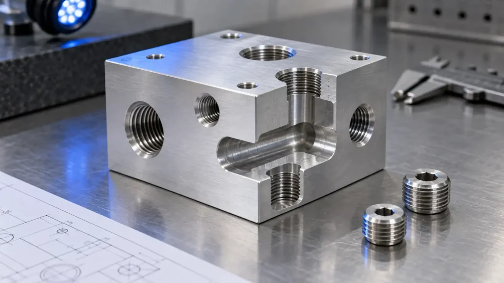
Direct answer. A machinable fluid-manifold drawing must define more than the external block and port positions. It needs a passage map, the geometry and finish of each functional port, a plan for intersecting-hole burrs, a defined closure for every process hole, and an acceptance method for the assembled flow path. The drawing should distinguish requirements on the machined block from requirements after plugs, seals and valves are installed. A leak-test result is meaningful only when the test medium, pressure, hold or stabilization method, acceptance criterion and test state are specified.
Map the flow circuit before placing holes
A manifold often uses cross-drilling to connect ports and cartridge cavities inside a compact block. A hole that is convenient to drill can also open into a neighboring circuit, create a dead-end volume, or require an exterior plug. Build a port-to-port connection table before release: name the inlet, outlet, return, vent and measurement ports; identify each internal passage; then mark every drill access and closure. For each passage, record its minimum required flow section and any restriction that belongs to the design. Do not infer hydraulic performance from a render alone. HydraForce's manifold-design materials show why cavities, cross-drills and plug locations are treated as a connected design problem, not independent hole features [1].
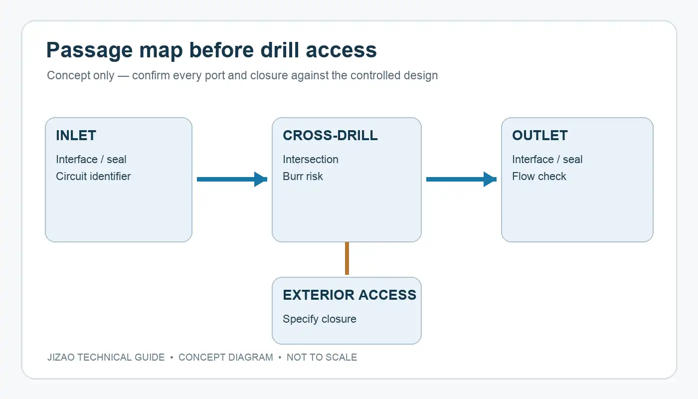
At an intersection, check whether the drill point breaks into the required passage with enough overlap while preserving wall material near adjacent cavities. Also decide whether a cross-hole edge is merely a burr-control feature or a sealing/flow surface. Those are different acceptance criteria. A clean CAD intersection does not prove that a manufactured edge is free of hanging burrs, chips or difficult-to-inspect debris.
Define ports and process-hole closures as interfaces
For each threaded or cartridge port, specify the applicable component interface, thread, sealing land, lead-in, surface condition and inspection basis. A nominal thread callout alone does not define an O-ring face or a port's axial position. If a standard cavity or plug is selected, cite its exact supplier drawing and revision in the controlled design package rather than reconstructing dimensions from a web image. Manufacturer plug catalogs are component-specific; a plug geometry that seals one cavity is not automatically interchangeable with another [2].
Cross-drills that start at an exterior face need a deliberate closure: removable plug, permanent expansion plug, threaded closure, or another approved design. The drawing or bill of materials should say which closure is used, who installs it, whether thread sealant or a washer is required, and which side is accessible for assembly and service. Installation torque, insertion depth and rework rules should come from the selected closure supplier or a qualified engineering procedure. Do not assign a generic torque to all plugs.
The closure can affect the pressure boundary, not just appearance. If the block supplier delivers an unassembled component, the final system leak requirement must not be silently imposed on the bare block. If the supplier is expected to deliver an assembled and tested manifold, show that explicitly in the RFQ and drawing package.
Design deburring and cleaning into the route
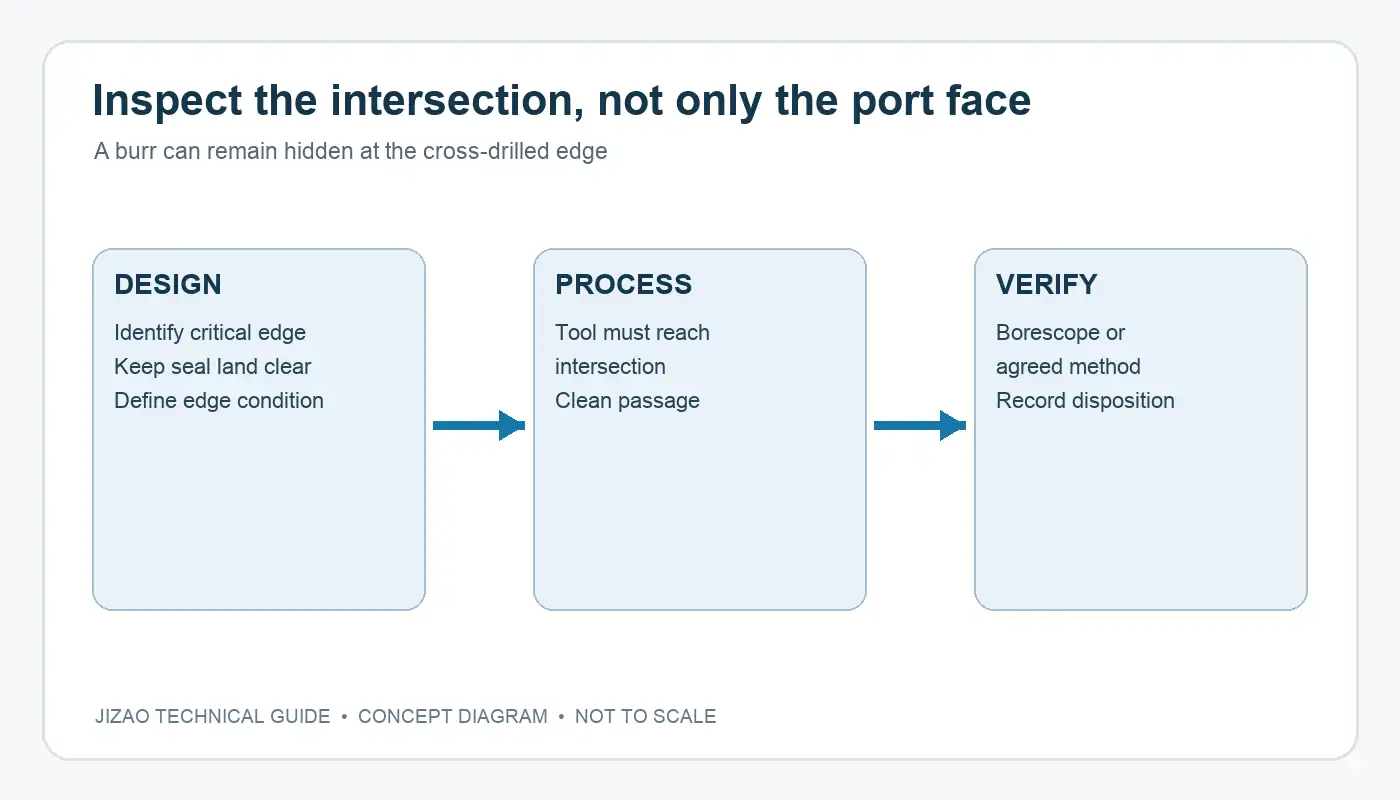
Intersecting holes can leave burrs that are invisible from an exterior face. Before choosing a deburring process, determine access from the main bore and from the intersecting passage, edge geometry, allowable edge break and whether the sealing land must remain untouched. Dedicated cross-hole deburring tools exist, but their suitability depends on bore access and geometry [3]. A blanket note such as “remove all burrs” is not a measurable substitute for identifying critical intersections.
For passages that carry fluid to sensitive components, specify the cleanliness requirement in a form the supplier can verify: contamination class or an agreed extraction-and-inspection method, the condition after plug installation, and what surfaces must be protected. Flushing may remove loose debris; it cannot repair a retained burr or an incorrectly drilled connection. Inspection access should be reviewed at design stage, for example a borescope path or sectioned first article when the geometry warrants it.
Write a test requirement that can be repeated
“Leak-free” is not a complete test specification. Define the assembly state, test medium, test pressure, stabilization or hold time, maximum permitted leakage or pressure change, temperature considerations, and ports that are blocked or connected during the test. If more than one circuit is isolated, state the sequence and boundary for each circuit. Pressure-decay, bubble and flow methods answer different questions and can have different sensitivity; select a method from the service risk and verification plan, not from a default shop routine.
A pressure test also does not automatically verify correct internal routing. A blocked passage can pass a leak test. Add a separate flow or continuity check when misconnection or obstruction is a relevant failure mode. Test fixtures and plugs need their own control because their leakage can be mistaken for product leakage. State whether the acceptance applies before or after cleaning, coating and final assembly.
What to send with an RFQ
Provide a controlled 3D model, 2D drawing with port and passage identifiers, component interface drawings, material and finish, closure BOM, deburr/cleanliness requirements, and test plan. Mark critical ports, pressure boundaries and surfaces that must remain uncoated or undamaged. Ask the supplier to flag inaccessible intersections, minimum-wall concerns, and any datum or setup changes before quoting. Multi-face machining can reduce some re-clamping, but it does not eliminate cross-hole burr, cleaning or verification work.
If the closure and test method are still undecided, request a design-for-manufacture review before asking for a fixed production quote. For related checks, see our CNC deburring guide and multi-face datum guide. To discuss a specific manifold drawing, send the controlled RFQ package; feasibility and test scope must be confirmed for that part.
Sources
- HydraForce, manifold-design resources — manufacturer explanation of cavities, cross-drills and manifold layout.
- HydraForce, manifold accessories — example of supplier-specific plug and accessory interfaces.
- HEULE, cross-hole deburring — manufacturer explanation of deburring intersecting bores.
Images are conceptual engineering illustrations. They are not customer parts, JIZAO production records or test evidence.






