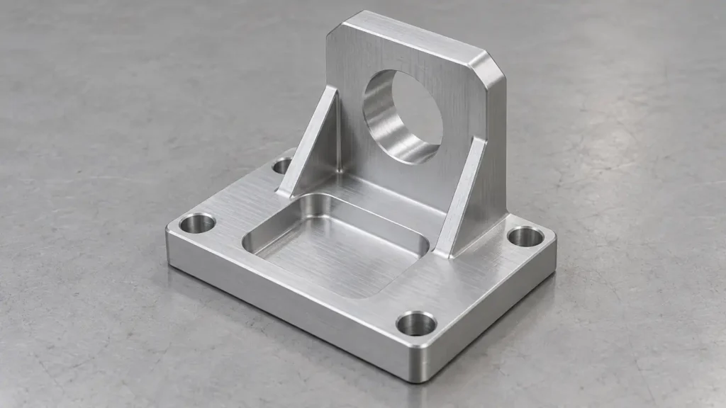
A useful CNC drawing review asks three questions about every important feature: what must it do, how can it be made, and how will conformity be verified? Start by marking the assembly interfaces, then trace their requirements through material condition, tool access, workholding and final inspection. The 12 DFM red flags below identify decisions that should be resolved before release—not universal bans on thin walls, deep holes or complex geometry.
The featured bracket is an AI-generated engineering concept, not a customer component or production record.
This checklist focuses on machined metal parts, including multi-face components considered for five-axis milling. Specialized micro-machining, nonmetallic materials and regulated-product requirements need additional review. An omitted note is not automatically an error: information may already be controlled by a referenced specification or authoritative model. The risk is an important requirement with no agreed interpretation.
Use the checklist as a release review, not a redesign order
Open the released drawing and matching model together. Identify the governing revision, units and document precedence before judging geometry; do not quietly resolve a disagreement in CAM.
For each flag, record the feature, its function, the open question, the proposed change or verification, and the person who can approve closure. A useful outcome may be a clearer note, a supplier-confirmed process, an inspection method or an approved design change. It need not be a simpler part.
| Review area | Flags | Evidence needed to close the question |
|---|---|---|
| Requirement definition | 1–3 | Material identity, functional limits and a consistent specification system |
| Cutting and support | 4–6 | Tool-envelope review, engagement strategy and the required measurement state |
| Holes and access | 7–9 | Depth definitions, manufacturing route and clearance verification |
| Setup and acceptance | 10–12 | Locating sequence, final-process condition and edge inspection |
Do not confuse three different capabilities. A machine’s positioning specification describes the machine under stated conditions. Process capability concerns the complete, repeatable route—including tooling, fixtures, material and thermal state. Inspection capability concerns whether the specified characteristic can be measured with suitable access and uncertainty. None proves the other two.
1. Material grade, condition or stock assumptions are unresolved
“Aluminum” or “stainless steel” can be enough for an early concept but may leave a released part open to materially different interpretations. Alloy identity alone also does not define temper, heat treatment or supplied condition. For aluminum extrusions, the Aluminum Extruders Council explains the distinction between alloy and temper; its guidance should not be extrapolated into a property guarantee for every product form.
The practical problem is that strength, cutting behavior, residual-stress history and finishing response can differ. A process developed for one condition may not transfer to another. Plate, extrusion, forging and casting are not interchangeable merely because the final model is identical.
Clarify the exact material and required final condition. Specify product form or stock orientation when function or stability requires it; otherwise let the supplier propose stock with an explicit assumption rather than dictating it unnecessarily. Ask what certification or traceability is required, and authorize substitutions through the design owner—not through a machinist’s visual identification.
2. A tight default tolerance is applied without a functional reason
A blanket close tolerance can make a clearance pocket as demanding as a locating bore. As the acceptable variation narrows, wear, thermal change, setup variation and measurement uncertainty consume more of the available margin. The consequence may be extra finishing and inspection, not simply a more accurate machine.
Do not widen limits because a feature “looks noncritical.” Clearance, assembly stack-up, wall strength and coating allowance may make a seemingly ordinary dimension important. Conversely, a tolerance copied from another drawing may add control with no useful function.
Classify the interfaces and justify their limits from fit or performance. Retain tight requirements where needed, define appropriate general limits elsewhere, and ask the supplier to identify which characteristics drive a special route. Discuss repeatability across the intended batch and replenishment cycle. A successful prototype or quoted machine accuracy is not evidence that all features will remain acceptable throughout production.
3. Size limits stand in for the actual geometric relationship
A bore can meet its diameter limits while its axis is tilted relative to the mounting face. A group of holes can each have acceptable size yet fail to align with a mating component. Size control, form control and orientation or location relative to datums answer different questions.
Choose the specification system explicitly. ASME lists Y14.5-2018 (R2024); ISO lists ISO 1101:2017 as current, confirmed in 2022. These official scopes do not make their defaults interchangeable. Interpret the released drawing under its stated system and edition rather than combining familiar symbols from both.
Identify the functional locating surfaces and feature relationships. Select the necessary controls with a competent drawing reviewer, then ask how the datums will be realized during acceptance inspection. A global best-fit alignment must not silently replace the specified datum relationship. The GD&T and CMM planning guide develops this question in more detail.
4. The internal corner radius has not been checked against the cutter
In a conventional milled pocket, the rotating cutter creates a rounded wall-to-wall corner. A small specified radius may force a smaller cutter; at the required reach, that can reduce stiffness. A radius that merely fits the cutter geometrically can still create high engagement as the tool rounds the corner. Haas identifies corner engagement as a chatter risk.
Distinguish that plan-view radius from a wall-to-floor fillet. A ball or corner-radius tool addresses different geometry; enlarging one radius does not automatically solve the other. A genuinely sharp functional corner may require relief, a different construction or another process.
Ask whether the corner locates a mating component or only clears it. If clearance permits, review a larger radius or localized relief while checking strength, sealing and assembly interference. If it cannot change, ask for the actual tool and process proposal at full depth. There is no universal radius-to-depth rule that substitutes for this review.
5. A deep, narrow pocket is reviewed without the complete tool envelope
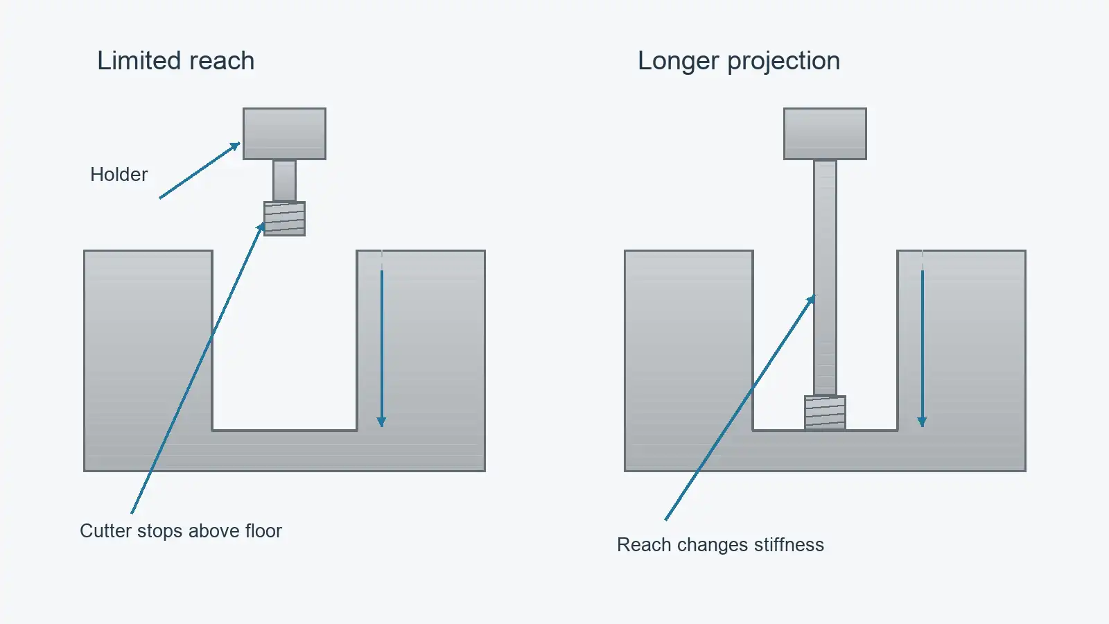
Corner radius is a local cutting constraint; pocket reach is an assembly constraint. Even when an end mill fits the opening, its usable cutting length, neck, shank and holder may prevent it from reaching the floor safely. More projection can provide clearance while worsening stiffness and increasing sensitivity to cutting load.
Sandvik Coromant’s milling selection guidance emphasizes secure clamping and short tool overhang. This is application guidance, not a fixed allowable pocket ratio.
Review the narrowest access section, full depth, stock remaining during the operation and holder clearance together. Opening a nonfunctional area, reducing local depth or allowing an alternate approach can help, but may change packaging or structural behavior. Ask the supplier to show a plausible tool envelope and chip-removal route—not merely a line representing the cutter axis. If long reach is unavoidable, agree how wall geometry and finish will be verified.
6. Thin walls or floors lack a support and release-state plan
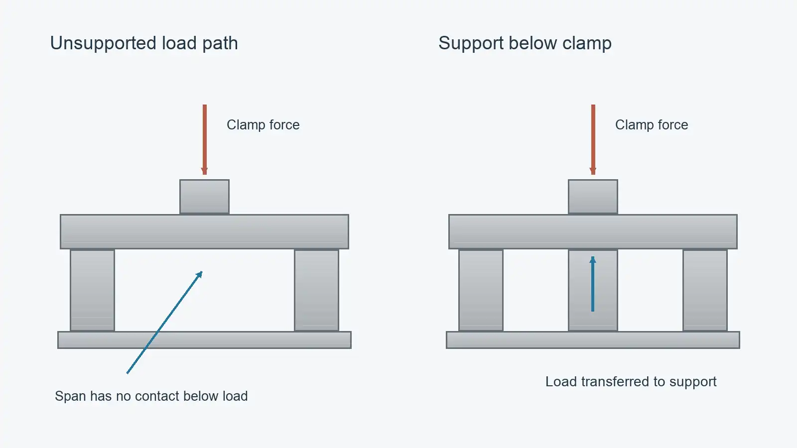
A thin feature is not inherently unmachinable. The risk is that cutting or clamping forces move it while its final geometry is being created. Removing surrounding stock can also change its support; residual stress and later processing may produce a different shape after release.
Stiffness depends on unsupported span, shape, material and boundary conditions—not wall thickness alone. Adding a rib may reduce movement but can affect mass, access and the mating envelope. A temporary support or staged finishing strategy may preserve the design at additional process cost.
Identify the surfaces that must be accepted in the free state and any functionally justified restrained condition. Ask how the part is supported during finishing, whether unclamping changes the critical measurement, and how a stable inspection setup will avoid forcing it into shape. Do not accept an in-fixture measurement as final proof without agreeing the required state. See the thin-wall deformation guide for the separate mechanisms.
7. Hole depth, geometry and inspection access do not describe the same requirement
A nominally deep hole can mean cylindrical depth or depth to the drill point. A diameter callout does not, by itself, explain every requirement for straightness, position, texture or a functional fit. Exit into an inclined face or intersecting passage can change the cutting conditions and access for cleanup.
Drilling, boring and reaming offer different routes; none should be chosen solely because the model shows a cylinder. Mitsubishi Materials’ drilling troubleshooting guidance identifies entry condition, tool length, runout and coolant as relevant variables. It is not a guarantee of hole performance.
Clarify the functional cylindrical depth, any permitted bottom shape, and the relationship to intersecting features. Ask how chips leave, how the exit is reached, and how the required characteristic is measured along the relevant region. An entrance diameter reading cannot establish the entire bore’s geometry. Add a section view when it resolves ambiguity; do not demand a flat drilled bottom unless function actually requires it.
8. Blind-thread engagement is confused with drilling and tooling space
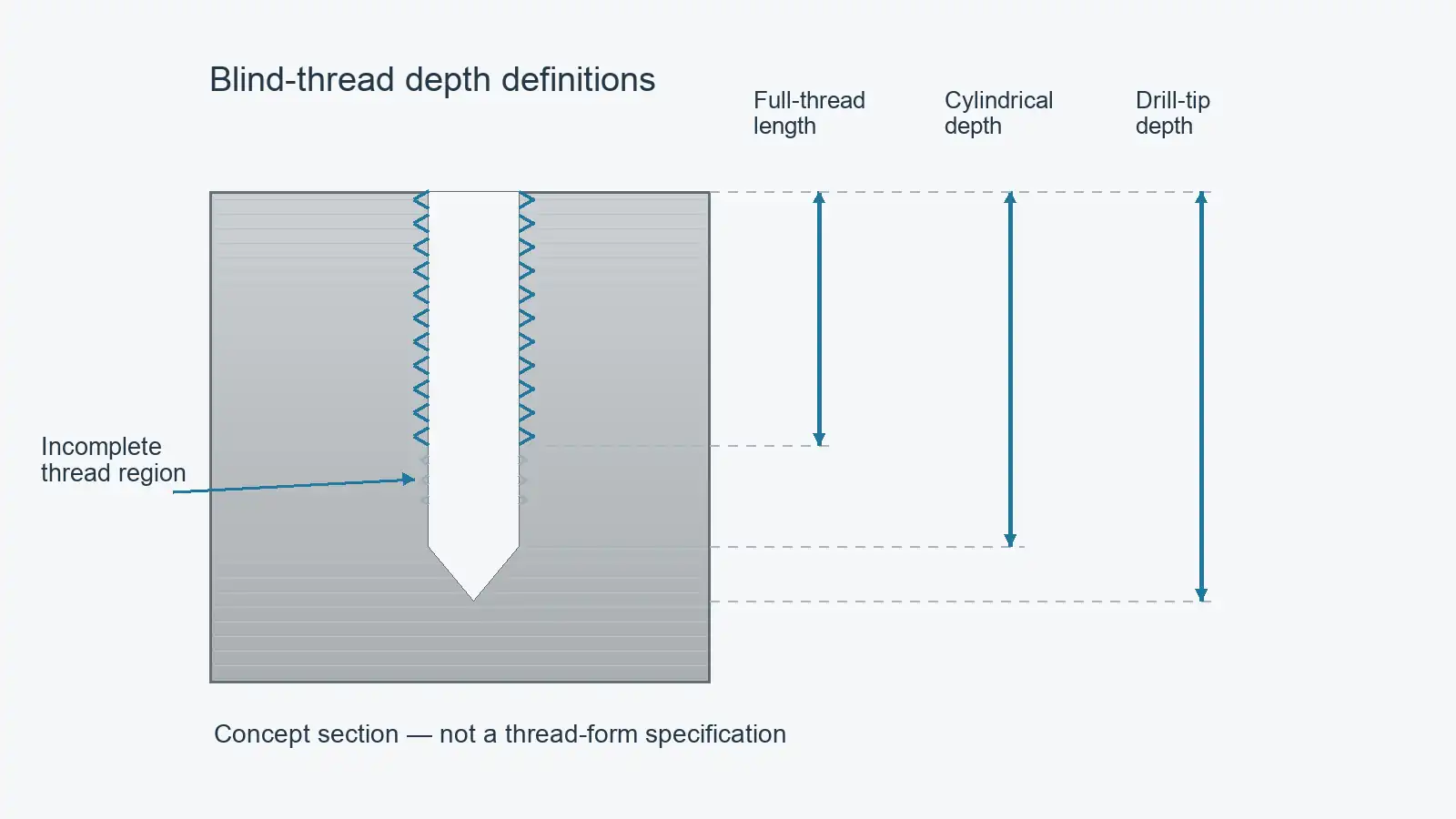
The useful full-thread length is not the same as the depth to the drill tip. A tap has a lead section that does not produce full-form threads immediately, and the selected operation needs appropriate clearance near the bottom. Cutting taps also need a chip-management strategy; forming taps and thread milling have different geometry and process requirements.
Depth margins depend on the thread, tool, material and route. “Use a bottoming tap” does not eliminate every clearance requirement, and simply drilling deeper can break into a protected passage or weaken the floor.
State the thread designation and tolerance class, required full-thread length, depth reference and maximum allowable bottom envelope. Check the fastener’s actual engagement after the mating stack, entry chamfer and any coating—not just its nominal length. Have the supplier resolve the remaining tooling space. Do not invent a standard extra-depth multiplier. Keep the physical floor and any prohibited breakthrough visible in the section.
9. Undercuts and angled features have no verified approach or clearance route
Being able to point the cutter at a feature is not the same as being able to machine it. An undercut may require a special cutter; an angled face may need indexing, simultaneous motion or another setup. The toolholder, spindle head, stock and fixture can obstruct a route that looks open in the finished-part model.
Autodesk’s shaft-and-holder guidance treats those envelopes separately. Its machine-simulation explanation also includes stock and fixtures. A simulation remains conditional on the correct geometry, configuration and checking settings.
Ask for approach and withdrawal clearance, including intermediate stock and the locating arrangement. Review a relief or alternate orientation only after checking function. Five-axis access may shorten a tool or reduce transfers on suitable geometry, but is not automatically the safer or cheaper route. The indexed versus simultaneous five-axis comparison helps frame that choice without prescribing it.
10. There is no stable locating, clamping and datum-transfer sequence
This flag concerns the physical setup, not the specification language in flag 3. A drawing can define excellent datums while leaving a part with no practical contact area at a necessary machining stage. Clamping a slender finished wall can distort it or damage a protected surface. Releasing and relocating the part introduces another relationship to control.
Ask what contacts remain after roughing and where the holding force goes. A sacrificial grip feature, soft jaws, dedicated fixture or revised operation order may resolve the problem. Each changes access, material use or setup effort; dedicated tooling may be easier to justify for recurring quantities than for a one-off.
Keep the functional datum intent independent of the temporary machining contacts, but show how the supplier transfers between them. Identify which related features should be produced together and how their relationship is verified afterward. “One setup” does not prove conformance, especially if deformation or an inaccessible face remains.
11. Texture and final dimensions have no agreed post-processing condition
“Smooth” and “anodized” do not define the same requirement. Visible cutter tracks, measured profile texture, flatness and cosmetic appearance need different acceptance criteria. Blasting, polishing, coating or heat treatment may change the geometry or surface state that is ultimately delivered.
For ISO profile-texture indication, ISO 21920-1:2021 is published; its official page also shows revision work underway. Select the required parameter and applicable evaluation rules rather than treating every roughness value as a complete functional specification. Do not apply ISO defaults to an ASME-based requirement by assumption.
Map sealing, sliding, locating, bonded and cosmetic surfaces separately. State when dimensions and texture apply, define masking or protected zones, and clarify required measurement access. The Aluminum Anodizers Council’s reference guide explains that anodic coating includes penetration and buildup; no single stock allowance should be inferred for every alloy and process. Agree final fit with the finishing route and inspect the delivered condition, not only the pre-treatment part.
12. Burr removal, edge geometry and protected edges are left ambiguous
“Deburr all edges” can mean removing raised material, adding an edge break, or rounding features. Those actions are not equivalent. Aggressive cleanup can damage a seal land, knife edge, bearing shoulder or datum contact even while removing the burr.
Identify the edges that may be broken and those that must retain defined geometry. Consider hole intersections and exit edges that are difficult to see or reach. Material, tool geometry and exit conditions affect burr formation; inspection must also detect loose material where it could compromise assembly or cleanliness.
Specify the permitted final edge condition and any prohibited material loss. Use a controlled edge specification if one already governs the part, and define exceptions explicitly. Ask how inaccessible edges are cleaned and verified without damaging neighboring features; agree viewing access, magnification or another suitable method when needed. Deburring is often a necessary operation, not evidence that the machining route has failed. The edge-requirements guide expands this acceptance discussion.
Turn the review into a controlled RFQ handoff
A red flag is closed when the requirement and its verification are agreed—not when someone says “we can machine it.” Send a matching model and drawing, material and final-condition requirements, prototype and recurring quantities, and the flagged features with their functional reasons. Include approved change options separately from requirements that cannot change.
For each unresolved item, request a concrete response: proposed tool or setup route, expected processing sequence, measurement method and state, and any assumption affecting the quotation. Record approvals in the released package. Supplier comments are not permission to change the design.
Use the STEP and PDF handoff guide to keep the files consistent. For multi-face geometry, review the five-axis machining service alongside the access and setup questions above. To request a drawing review, contact JIZAO with a nonconfidential requirement summary first; arrange an appropriate controlled channel before sharing restricted CAD or drawings.
The aim is not to eliminate difficult features. It is to preserve their function while making the manufacturing assumptions, approval responsibilities and acceptance method explicit.






