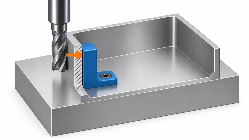
Short answer
Control thin-wall aluminum deformation by identifying what is moving and when. Cutting-force deflection, clamping deformation, residual-stress redistribution, and thermal effects require different responses. A robust plan usually combines suitable material condition, balanced stock removal, staged roughing and finishing, low-distortion support and clamping, controlled cutting-force direction, stable thermal conditions, and inspection after release. There is no universal minimum wall thickness, clamp pressure, feed, or speed: the correct values depend on geometry, alloy and temper, tool reach, machine dynamics, surface requirements, and tolerance.
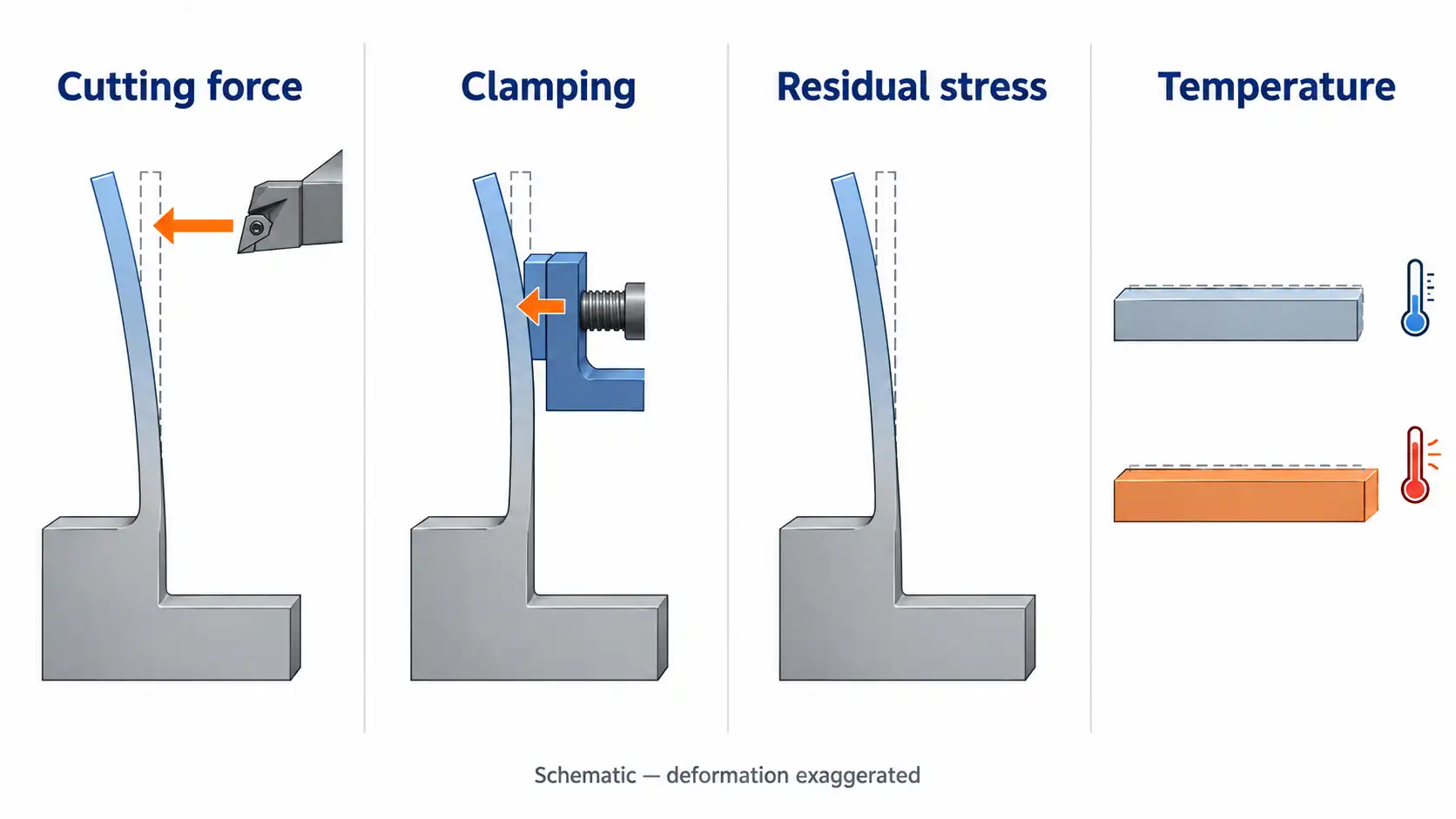
“The part warped” can describe four different mechanisms
Thin walls have low stiffness, but low stiffness alone does not identify the cause of a bad result. The timing and direction of movement provide the first diagnostic clue.
- Cutting-force deflection occurs while the tool is engaged. The wall bends under the instantaneous load and may spring back after the cutter passes. Tool geometry, engagement, direction of force, tool reach, support, and the remaining wall stiffness all matter.
- Clamping deformation occurs when the fixture forces the workpiece into a temporary shape. A feature measured while clamped may appear acceptable, then move after the clamps are released.
- Residual-stress redistribution occurs as machining removes material that previously balanced internal stresses in the stock. The workpiece may move between operations or after release even when cutting forces were well controlled.
- Thermal deformation comes from changes in the part, tool, fixture, or machine as heat input and ambient conditions change. A transition from heavy roughing to finishing changes the mechanical and thermal load on the machine, as HEIDENHAIN notes in its discussion of machine-tool accuracy (HEIDENHAIN accuracy guidance).
These mechanisms can occur together. Increasing clamp force may suppress vibration but increase release movement. A very light finishing pass may reduce force but rub if the tool or cutting condition is unsuitable. Leaving more stock for later can preserve stiffness, but an unbalanced stock pattern may allow residual stress to move the part. Diagnose before adjusting a single parameter.
Diagnose by process stage
Use observations from more than one state. Measuring only the final rejected part often hides the source.
| Observation | Likely mechanisms to investigate first | Useful comparison |
|---|---|---|
| Wall appears to move only while the tool is engaged | Cutting-force deflection, chatter, tool deflection | Change support, force direction, engagement, or tool reach and observe the response |
| Dimension is acceptable while clamped but changes after release | Clamping deformation, residual stress | Measure in-fixture and after a controlled release-and-rest sequence |
| Part moves progressively after major stock removal | Residual-stress redistribution, unbalanced machining | Compare removal sequence, stock symmetry, and material condition |
| Results vary with warm-up, cycle order, or time in the shop | Thermal effects in machine, workpiece, fixture, or measurement | Record process and measurement temperatures and timing |
| One local wall is unstable while the rest of the part is consistent | Local stiffness, unsupported cutting load, tool engagement | Map tool-force direction to available fixture support |
This table is a starting point, not a root-cause verdict. Confirm the hypothesis with a controlled process change and an agreed measurement method.
Begin with material condition and stock strategy
All aluminum stock is not equivalent from a distortion perspective. Alloy, temper, product form, prior processing, thickness, and supplier controls influence the starting condition. Stress-relieved tempers and tooling plate products are commonly selected when machining stability is important. For example, Kaiser’s engineering plate literature identifies low residual stress and flatness as material characteristics and lists T651 plate offerings (Kaiser Aluminum engineering plate). That is evidence that material condition is a process input—not a guarantee that a finished part will remain flat.
Specify the required alloy, temper, product form, and certification level deliberately. If the design permits alternatives, involve material and manufacturing specialists before freezing the selection. Do not substitute a marketing phrase such as “low stress” for traceability to the ordered condition.
The stock-removal plan should then preserve stiffness as long as practical. Avoid fully finishing one weak region while a large, rigid mass remains elsewhere unless analysis or testing supports that sequence. Roughing opposite sides or alternating regions may help balance release, but the correct pattern depends on geometry and access. Leave intentional stock for semi-finishing and finishing, and define when the part may be released, reoriented, or allowed to stabilize.
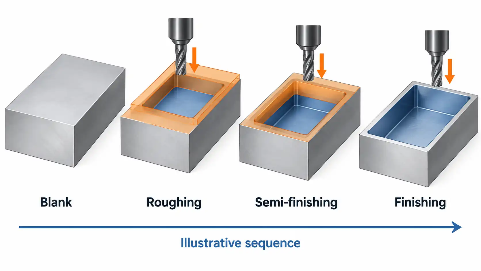
Separate roughing, stabilization, semi-finishing, and finishing
A staged process gives the part opportunities to reveal movement before final material is removed. A typical planning logic is:
- Establish stable locating surfaces and verify stock condition.
- Rough the major cavities or material masses while preserving ribs, tabs, or other temporary stiffness where appropriate.
- Release or relax the workholding only if the process plan calls for it, then re-establish the datum in a controlled way.
- Semi-finish critical walls and interfaces, leaving a defined finishing allowance.
- Finish related features in a thermally and mechanically stable sequence.
- Inspect both the controlled in-process state and the specified final free state where relevant.
This is a planning framework, not a fixed recipe. Some geometries require one stable clamping; others benefit from planned relaxation or symmetric removal. Parts subject to heat treatment, coating, anodizing, or other post-machining processes may need additional allowance and validation because later operations can change the final condition.
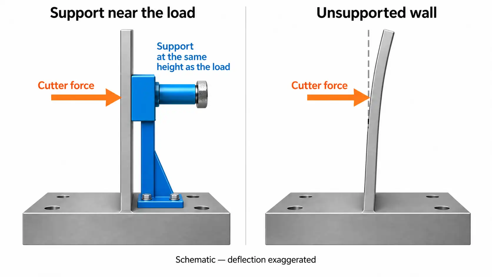
Direct cutting forces into support, not into a free wall
Toolpath and tooling choices should be evaluated as a force system. The wall, tool, holder, fixture, and machine form a flexible chain. Shorter practical tool overhang, secure workholding, suitable cutter geometry, and controlled engagement generally improve stability. Sandvik Coromant’s milling guidance explicitly treats thin-wall conditions, component rigidity, clamping, and tool overhang as application variables rather than a single universal setting (Sandvik Coromant milling tools catalog).
Whenever possible, arrange the cut so the dominant force is reacted by a support close to the machining zone. Avoid pushing an unsupported wall away from the fixture. Consider the direction of conventional or climb milling within the full machine, tool, and workholding context; there is no blanket rule that one direction solves every thin-wall feature.
Tool geometry can change both the magnitude and direction of force. Seco’s thin-wall tooling discussion, for example, links cutter geometry and axial angle to reduced cutting forces in unstable setups (Seco thin-wall tooling example). Treat this as a design principle to evaluate with the selected tool supplier and actual application, not as a product endorsement or a guaranteed result.
Support the workpiece without forcing it into shape
Good workholding constrains the part, resists cutting loads, and remains repeatable without over-constraining a weak wall. Place primary supports under load paths and locate from surfaces that can seat consistently. Apply only the clamp force needed for security, distributed so it does not create a hidden bend.
Adjustable or self-equalizing work supports can help when a surface varies or when support must approach the workpiece without preloading it. Römheld describes hydraulic work supports as self-adjusting rests intended to compensate for surface irregularity, vibration, and deflection under machining load (Römheld work-support description). The engineering caution is important: a support should stabilize the actual position; it should not jack a flexible wall into a nominal position before locking.
Soft jaws, vacuum fixtures, adhesive workholding, sacrificial tabs, low-melting media, or custom nests can be appropriate in some applications, but each method changes the risk profile. Review holding force, contact pressure, contamination, access, release method, surface protection, and compatibility with downstream processes before selection.
Manage thermal state and measurement state together
Thermal planning is not limited to coolant selection. Roughing intensity, spindle and axis activity, pauses, workpiece handling, shop conditions, and the delay before inspection can all change the measured state. Define whether critical dimensions are evaluated immediately, after a stabilization period, or under a specified standard condition. The answer must come from the drawing, quality plan, applicable standard, and risk—not an assumed shop habit.
Inspection should reveal clamp-induced movement rather than hide it. For characteristics that function in the free state, include a free-state measurement after controlled release. If the part functions while assembled or constrained, define the restraint condition explicitly and make sure it represents the design requirement. Record the fixture state, temperature-related conditions, support locations, and measurement timing when they affect interpretation.
Build a controlled trial, not a parameter myth
Thin-wall process development works best when one suspected contributor is changed at a time. Record material identity and condition, blank orientation, operation sequence, tool and holder, engagement strategy, workholding state, relevant temperatures, and measured results. Compare released and clamped measurements where appropriate. A small, structured trial provides more transferable knowledge than copying an unsupported speed or wall-thickness rule from another geometry.
Before production approval, confirm:
- the drawing defines the required free or restrained state where necessary;
- material condition is traceable;
- roughing and finishing sequences preserve adequate stiffness;
- clamp and support loads do not force the part into acceptance;
- tool reach and force direction match the available support;
- thermal and stabilization conditions are controlled or recorded;
- the inspection method can resolve the specified characteristic;
- post-machining processes are represented in validation.
Conclusion
There is no single cure for thin-wall aluminum deformation because “deformation” is not one mechanism. Separate cutting deflection, clamping deformation, residual-stress redistribution, and thermal effects. Then match the response to the cause: improve support and force direction, revise the stock-removal sequence, select and verify material condition, stabilize the thermal process, and inspect the specified final state. The winning process is the one demonstrated for the actual geometry and requirement—not the one with the most aggressive universal rule.
Ask about a non-confidential engineering question: Share only the broad part category, material family, quantity band, deformation stage, and affected feature type. Do not send drawings, links, exact dimensions or tolerances, project identifiers, or other confidential details through the current form. Arrange an approved secure channel before any detailed file exchange.






