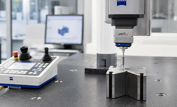
Surface roughness is more than a cosmetic detail. In CNC machining, 5-axis machining, 3D printing, vacuum casting, and surface finishing, the roughness value you specify can affect sealing, friction, coating adhesion, wear resistance, appearance, inspection requirements, and final manufacturing cost.
For engineers and buyers, a surface roughness chart helps translate drawing requirements such as Ra 3.2 μm, Ra 1.6 μm, or Ra 0.8 μm into practical manufacturing expectations. The key is not always choosing the smoothest finish. The right approach is choosing the most suitable surface finish for the part’s function, material, tolerance, and budget.
At JIZAO CNC, our engineers review drawings, materials, tolerances, surface finish requirements, quantity, and application before quotation, helping customers avoid over-specification and reduce production risk.
What Is Surface Finish?
Surface finish describes the overall condition and texture of a part’s surface. It includes three major elements: roughness, waviness, and lay. ASME B46.1 describes roughness as finer-spaced irregularities, waviness as more widely spaced surface texture, and lay as the predominant direction of the surface pattern.
Surface Roughness
Surface roughness refers to the small peaks and valleys left on a surface after machining, grinding, polishing, additive manufacturing, casting, or other production processes. It is usually measured in micrometers or microinches.
Waviness
Waviness refers to larger, more widely spaced surface variations. These may come from machine vibration, tool deflection, thermal movement, workholding instability, or material deformation.
Lay
Lay is the main direction of the surface pattern. For example, turning usually creates circular lay marks, while milling often creates directional tool paths. Lay can matter for sealing surfaces, sliding parts, fluid flow, and visual appearance.
Why Surface Roughness Matters in Engineering Parts
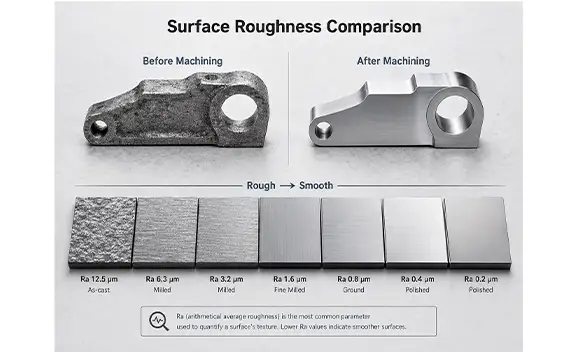
Surface roughness can influence both function and cost. ZEISS notes that surface texture affects friction, sealing, adhesion, lifespan, aesthetics, and optical properties, and ISO 21920 is used to improve consistency in surface specification and evaluation.
A suitable surface finish can help with:
- Reducing friction between moving parts
- Improving sealing performance for O-rings, gaskets, and fluid systems
- Supporting coating, anodizing, painting, or plating adhesion
- Improving cosmetic appearance
- Reducing premature wear
- Supporting more stable assembly and fit
- Avoiding unnecessary polishing, grinding, or secondary finishing costs
For example, a hidden non-mating bracket face may not need Ra 0.8 μm. But a sealing groove, bearing surface, optical housing, or precision sliding interface may require a much smoother and more tightly controlled finish.
The Common Mistake: Over-Specifying Surface Roughness
Many drawings apply the same surface roughness requirement to every face of a part. This often increases cost without improving function.
A practical engineering review should ask:
- Which surfaces are cosmetic?
- Which surfaces are functional?
- Which surfaces contact other parts?
- Which surfaces need sealing, sliding, coating, or bonding?
- Which roughness values must be inspected and documented?
- Can some non-critical surfaces use a standard machined finish?
For CNC machining, a general machined surface may be enough for many structural parts. Tighter roughness such as Ra 0.8 μm, Ra 0.4 μm, or Ra 0.2 μm may require slower machining, sharper tools, additional passes, polishing, grinding, lapping, or special inspection.
JIZAO engineering tip: Do not specify ultra-smooth finishes everywhere. Mark only the critical surfaces on the drawing and allow standard machining marks on non-functional areas whenever possible.
How to Measure Surface Roughness
Surface roughness is commonly measured by contact or non-contact methods. A stylus profilometer is one of the common measurement tools; ASME explains that a stylus with known tip radius moves across the surface and records height data, which is then filtered to separate roughness from waviness. NIST also describes mechanical stylus profilometer measurement using a diamond tip across the surface for surface texture and microform measurements.
Contact Measurement
A contact stylus profilometer moves a small probe across the surface. The instrument records height variations and calculates parameters such as Ra, Rz, Rq, or Rt.
This method is useful for many machined metal and plastic parts, but the measurement direction, cutoff length, sampling length, and surface condition must be controlled.
Non-Contact Measurement
Non-contact methods use optical or laser-based systems to measure the surface without touching it. These methods are useful for delicate, soft, highly polished, or micro-feature surfaces.
Surface Roughness Comparison Samples
Surface roughness comparator plates allow quick visual and tactile comparison. They are useful for workshop reference but should not replace formal measurement when a specific Ra or Rz value is required on a technical drawing.
In-Process Control
For precision CNC machining, roughness control starts before final inspection. Tool sharpness, feed rate, spindle speed, vibration, coolant, material condition, tool path strategy, and workholding all affect the final surface.
Surface Roughness Symbols and Parameters
[Image: Technical drawing with surface roughness symbols and Ra callouts]
Surface roughness symbols help engineers communicate surface requirements clearly on technical drawings. ISO 21920 defines methods, terminology, drawing symbols, and parameters for surface texture specification; common parameters include Ra and Rz.
Ra – Average Roughness
Ra is the most common surface roughness parameter. It represents the average absolute deviation of the surface profile from the mean line over the evaluation length. ASME B46.1 defines Ra as the average of absolute profile height deviations within the evaluation length.
Ra is widely used because it is simple and easy to compare. However, Ra alone does not show whether the surface has isolated deep scratches, sharp peaks, or unusual texture.
Rz – Average Maximum Height
Rz focuses more on peak-to-valley height. It is often more sensitive to deeper valleys and higher peaks than Ra. For sealing, sliding, or fatigue-sensitive applications, Rz may provide useful additional information.
Rq or RMS
Rq, sometimes called RMS roughness, uses a root mean square calculation. It is more sensitive to larger peaks and valleys than Ra. However, Ra and Rq should not be treated as perfectly interchangeable.
Rt and Rmax
Rt and Rmax describe larger peak-to-valley values. These can be useful when isolated scratches, burrs, or surface defects may affect performance.
Surface Roughness Conversion Chart
The table below gives practical reference values commonly used in machining and surface finish discussions. Always confirm the final requirement on the engineering drawing and define the measurement standard when roughness is critical.
| Ra μm | Ra μin | Approx. Finish Grade | Typical Use |
|---|---|---|---|
| 25.0 | 1000 | Very rough | Saw-cut, rough forged, non-critical clearance surfaces |
| 12.5 | 500 | Rough | Heavy machining, rough clearance areas |
| 6.3 | 250 | Medium rough | General clearance surfaces, non-cosmetic areas |
| 3.2 | 125 | Standard machined | Common CNC milled or turned surfaces |
| 1.6 | 63 | Good machined finish | Mating surfaces, better controlled machining |
| 0.8 | 32 | Fine machined finish | Precision mating, sealing-related surfaces |
| 0.4 | 16 | Very fine finish | Bearing areas, high-quality sealing or sliding surfaces |
| 0.2 | 8 | Precision finish | Optical, gauge, or high-precision functional surfaces |
| 0.1 | 4 | Ultra-fine finish | Special precision applications |
| 0.05 | 2 | Superfinish | Highly controlled precision surfaces |
| 0.025 | 1 | Mirror/superfinish | Gauge blocks and extremely demanding applications |
Surface Roughness Chart for CNC Machining Cost Control
| Ra Value | Finish Description | Typical Process | Engineering Recommendation |
|---|---|---|---|
| Ra 6.3 μm | Rough machined | Rough milling, drilling, turning | Use for non-contact and hidden clearance surfaces |
| Ra 3.2 μm | Standard CNC finish | General CNC milling and turning | Good default for many structural parts |
| Ra 1.6 μm | Controlled machined finish | Fine milling or turning | Suitable for many mating surfaces |
| Ra 0.8 μm | Fine finish | Fine machining, grinding, polishing if needed | Use only where sealing, sliding, or precision fit requires it |
| Ra 0.4 μm | High-quality finish | Grinding, polishing, lapping | Suitable for high-load, bearing, or demanding functional surfaces |
| Ra 0.2 μm | Precision finish | Fine grinding, polishing, lapping, special machining control | Use for highly demanding applications such as optical or precision assembly surfaces |
JIZAO has produced precision 5-axis machined components with demanding surface quality, including a miniature camera module component requiring Ra 0.2 μm for precise assembly and optical integration.
Recommended Surface Roughness by Manufacturing Process
CNC Milling and Turning
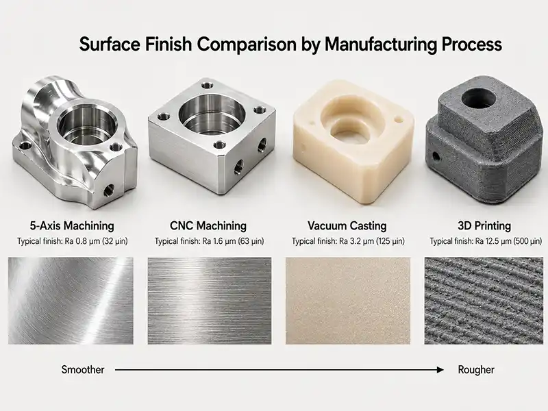
CNC milling and turning can produce a wide range of surface finishes depending on tool path, feed rate, material, cutting tool, coolant, and machine rigidity. A typical machined finish may be suitable for many functional prototypes and production parts.
JIZAO provides CNC milling, turning, and precision machining for prototype and production parts, with tolerances as tight as ±0.025 mm for eligible projects.
5-Axis CNC Machining
5-axis machining is useful for complex geometries, multi-face features, curved surfaces, and parts that benefit from fewer setups. Reducing setups can help maintain alignment and consistency across complex surfaces.
JIZAO supports 5-axis machining for complex geometries and high-precision parts, including thin-wall UAV components, robotic parts, medical components, and optical-related parts.
3D Printing
3D printed surfaces vary significantly by process. SLA parts can provide smoother appearance models, while SLS, MJF, and FDM may show more visible texture or layer lines. Post-processing may be needed for cosmetic or functional surfaces.
JIZAO offers rapid prototyping through SLA, SLS, MJF, and FDM 3D printing for design validation and functional testing.
Vacuum Casting
Vacuum casting is often used for low-volume plastic parts, appearance models, functional validation, and bridge production. Surface quality depends on the master model, mold quality, material, and finishing requirements.
JIZAO provides vacuum casting for low-volume plastic part production, typically recommended for 10–100 pcs per part.
Post-Processing and Surface Finishing
Surface roughness can change after anodizing, bead blasting, polishing, painting, powder coating, plating, or other finishing operations. For tight functional surfaces, define whether the roughness requirement applies before or after final finishing.
How to Choose the Right Surface Roughness
1. Start with the Part Function
Do not choose Ra values only by appearance. A hidden support bracket, a cosmetic cover, a sealing groove, and a bearing seat all need different surface decisions.
2. Separate Critical and Non-Critical Faces
Instead of applying Ra 0.8 μm to the entire part, specify it only on surfaces that truly need it. Allow standard machining finish on non-critical areas.
3. Match Roughness with Tolerance
A tight dimensional tolerance and a fine surface finish often increase machining complexity together. When both are required on the same feature, make sure the function justifies the cost.
4. Consider Material Behavior
Aluminum, stainless steel, titanium, brass, copper, PEEK, and engineering plastics machine differently. Some materials are easier to finish cleanly, while others may require slower cutting, sharper tools, or extra finishing.
5. Define Inspection Requirements
If roughness is critical, indicate the measuring location, direction, parameter, and standard. This helps prevent misunderstandings between design, machining, and quality inspection teams.
Common Surface Roughness Problems and How to Prevent Them
Tool Marks
Visible tool marks often come from feed rate, tool geometry, step-over, or tool wear. A finishing pass can improve the surface.
Chatter Marks
Chatter may come from insufficient rigidity, long tool reach, thin-wall vibration, unstable workholding, or aggressive cutting parameters.
Burrs and Sharp Edges
Burrs can affect assembly, sealing, safety, and appearance. Add clear deburring or edge-break requirements when needed.
Wrong Roughness Callout
A common mistake is applying tight roughness to every surface. This increases cost and may delay production.
Measurement Disagreement
Different cutoff lengths, measurement directions, filters, or instruments can produce different results. ASME notes that filter settings can significantly affect roughness and waviness values.
JIZAO CNC Surface Finish and Quality Support
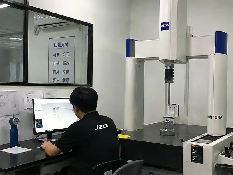
JIZAO is a Shenzhen-based custom parts manufacturing company supporting CNC machining, 5-axis machining, 3D printing, and vacuum casting for global customers. Our quality team performs pre-production, in-process, and final inspection, and inspection documents such as FAI, dimensional reports, material compliance documents, and functional test records are available upon request.
For surface roughness-sensitive projects, we recommend providing:
- 2D drawings with Ra/Rz callouts
- 3D CAD files such as STEP or IGES
- Material and surface finish requirements
- Critical surface notes
- Quantity and application
- Inspection report requirements
- Whether roughness applies before or after finishing
This allows our engineers to review manufacturability, suggest practical improvements, and quote the project more accurately.
Conclusion
Surface roughness is a key part of product performance, but smoother is not always better. The best surface finish is the one that meets the functional requirement without adding unnecessary machining, polishing, grinding, inspection, or finishing cost.
Use a surface roughness chart as a practical guide, but always connect Ra or Rz values to the real function of the part. For CNC machined parts, 5-axis components, prototypes, and low-volume production, a clear drawing and early engineering review can help you achieve the right balance between performance, quality, lead time, and cost.
Ready to start your project? Send your 3D files, 2D drawings, material, quantity, and surface finish requirements to JIZAO CNC for an engineering review and quotation.
FAQ: Surface Roughness Chart
What is surface roughness?
Surface roughness is the small-scale texture on a part surface, usually caused by machining, grinding, polishing, casting, additive manufacturing, or material condition.
What is the difference between surface finish and surface roughness?
Surface finish is the broader term. It includes roughness, waviness, lay, appearance, and other surface characteristics. Surface roughness is one measurable part of surface finish.
What does Ra mean?
Ra means average roughness. It is the average absolute deviation of the surface profile from the mean line over the evaluation length.
Is Ra 3.2 μm good for CNC machining?
Ra 3.2 μm is a common machined finish for many CNC milled and turned parts. It is often suitable for structural, non-sealing, and general functional surfaces.
Is Ra 1.6 μm smoother than Ra 3.2 μm?
Yes. Lower Ra values indicate a smoother surface. Ra 1.6 μm is smoother than Ra 3.2 μm.
When should I specify Ra 0.8 μm or smoother?
Use Ra 0.8 μm, Ra 0.4 μm, or Ra 0.2 μm only when the part function requires it, such as sealing, sliding, bearing contact, optical assembly, or high-precision mating surfaces.
Can anodizing, plating, or coating change surface roughness?
Yes. Surface finishing can change the final surface texture. If the final roughness is critical, specify whether the requirement applies before or after finishing.
How do I avoid unnecessary surface finish cost?
Mark only critical surfaces with tight Ra or Rz requirements. Allow standard machined finish on non-critical surfaces and ask for DFM feedback before production.
Can JIZAO CNC inspect surface roughness?
JIZAO provides drawing-based quality inspection and can provide inspection reports upon request. For roughness-critical parts, include the required roughness parameter, measurement area, and inspection requirement in your drawing or RFQ.






