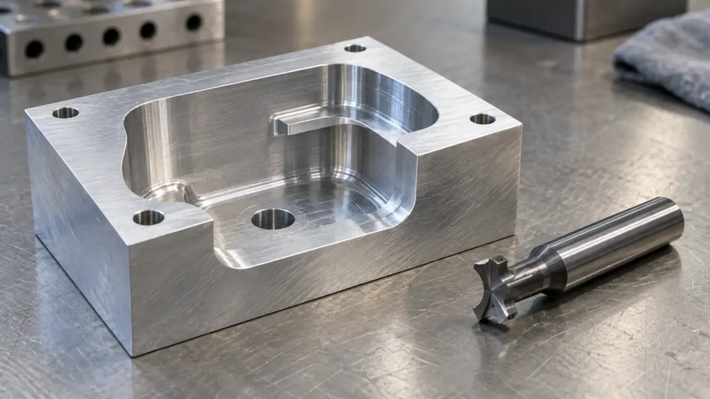
Five-axis motion can expose an undercut to a cutter, but it cannot make solid metal, the tool shaft or the holder disappear. The practical test is whether the complete tool assembly can enter, cut, retract and clear the part and fixture while producing a measurable functional feature. Some undercuts need only a shaped cutter or an indexed 3+2 orientation; others justify simultaneous motion, sinker EDM or a design change. Select the route from geometry and acceptance requirements, not axis count alone.
Define the hidden feature and why it exists
An undercut is a feature whose surface is not visible to a straight tool approach from a chosen direction. It might be a retaining groove below a lip, a relief behind a wall, a reverse-facing sealing surface or an internal clearance. First mark which surfaces actually perform the retaining, sealing or locating function. If a hidden corner is only a clearance, its exact shape may be negotiable; if it retains a ring, tool access cannot be improved by casually removing the lip.
Ask for a section view through the difficult feature, the entrance opening, undercut depth, required side-wall and floor geometry, edge condition and the relationship to the part's functional datums. The 3D model shows the volume, but the drawing must distinguish controlled surfaces from free clearance. A general inside-corner radius rule is not enough: the difficulty here is the tool's approach and escape path behind the overhang.
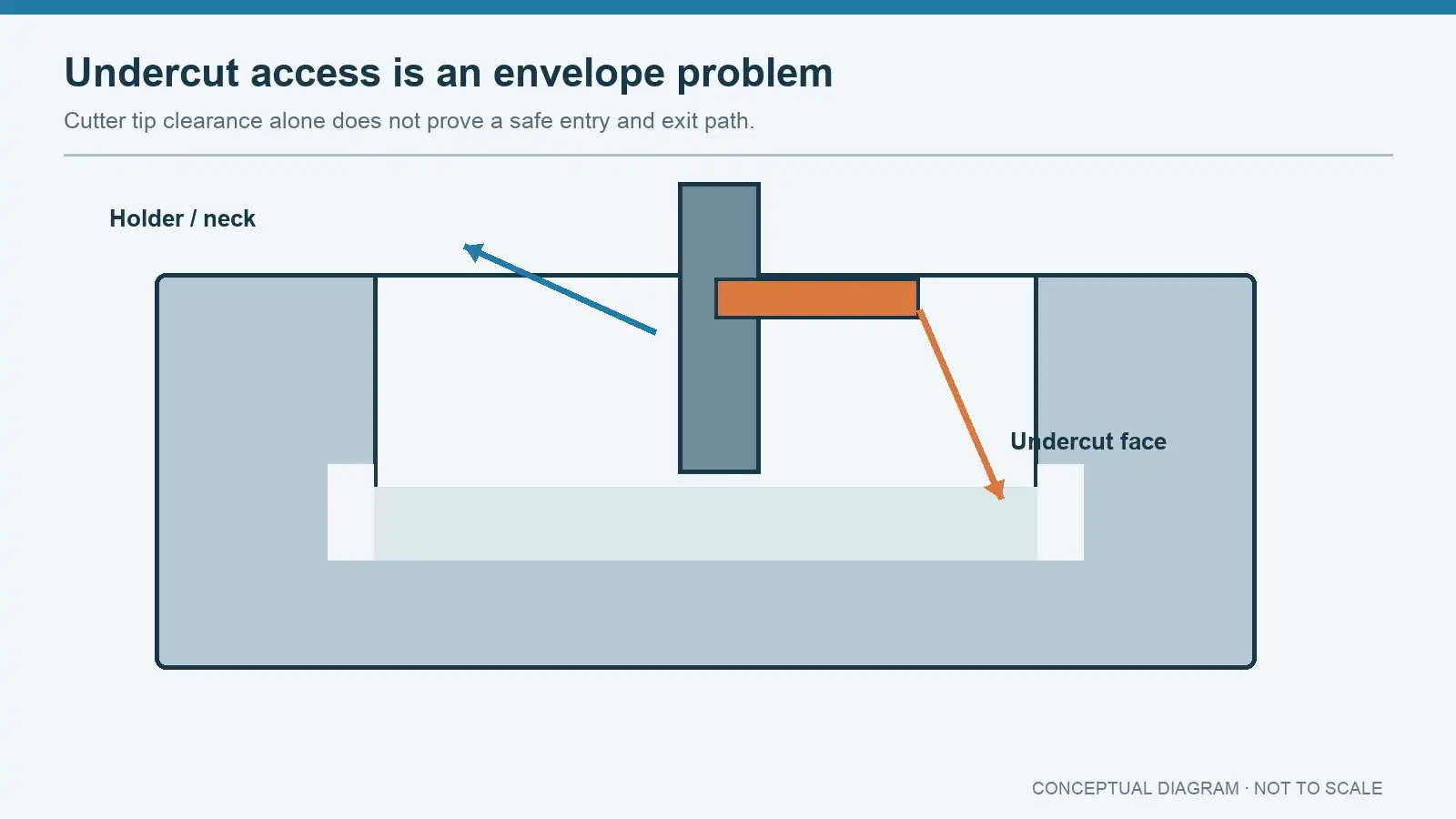
Check cutter, neck, holder and fixture as one envelope
A cutter tip that reaches a face on screen may still leave an unusable toolpath. Its neck can rub the lip, the holder can collide with the outer wall, or the tool can be unable to retract without gouging. Autodesk's shaft and holder modes distinguish collision handling for the shaft and holder. That is a programming aid, not proof that a particular machine and fixture will safely cut the real part.
The entrance size and pocket depth set the available tool diameter and reach. A long, slender tool tends to be less stiff; reducing engagement or changing the tool form may help, but can add cycle time or leave an uncut corner. A T-slot or undercutting cutter approaches through an opening and cuts laterally behind the lip. Manufacturer examples such as Micro 100's undercutting end mills show that specialized cutter geometry exists, but a catalogue image does not validate the selected cutter's reach, material, cutting forces or corner form for a new part.
Model the stock, final part, complete cutter assembly and actual holding hardware. Check the cutting move and the rapid/linking motions. Autodesk's 3+2 guidance discusses holder-limited regions and fixture avoidance; it still requires the programmer to verify the chosen arrangement.
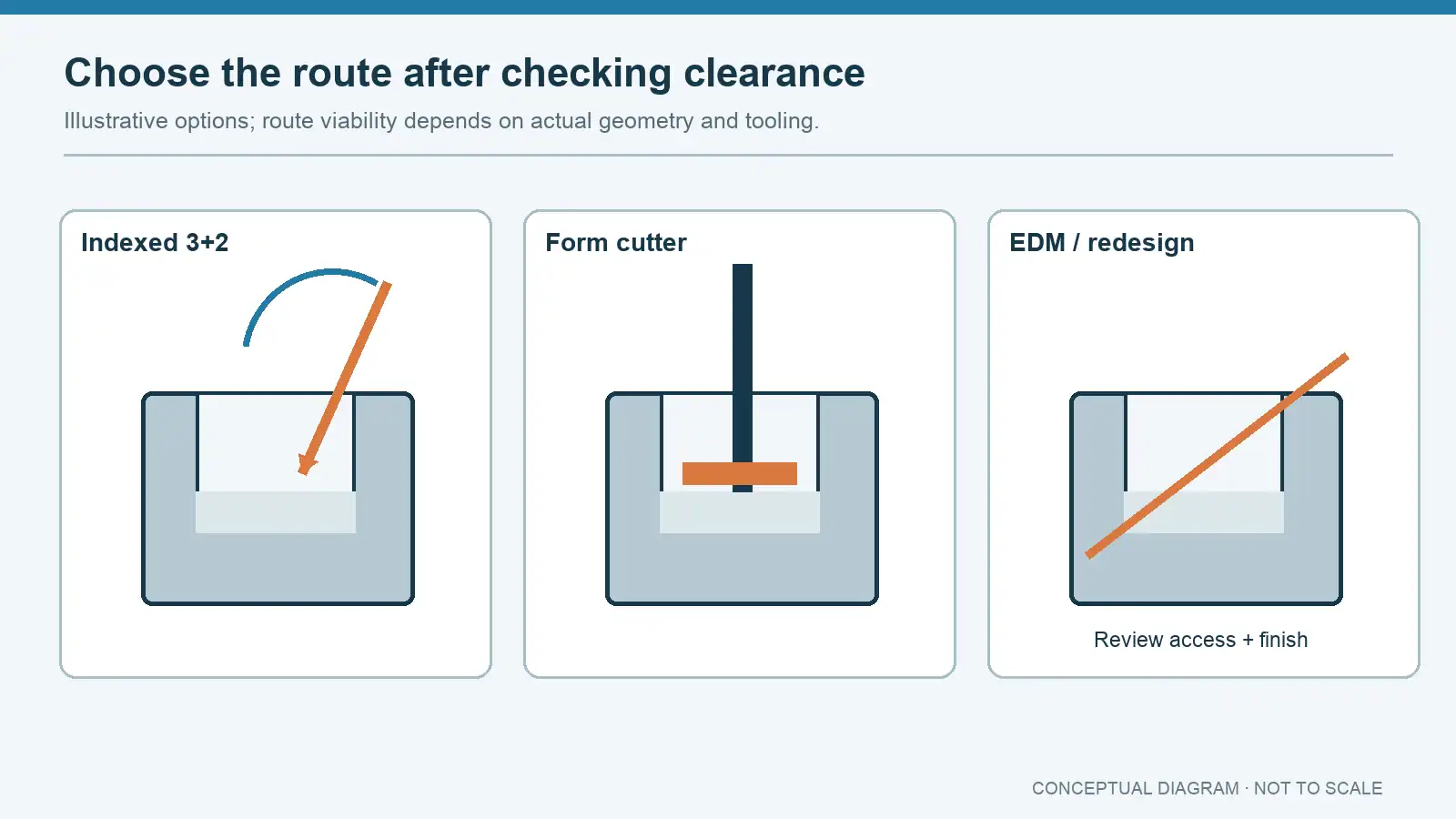
Choose among fixed-angle access, continuous motion and other routes
| Route to investigate | When it may help | Limiting question |
|---|---|---|
| Three-axis with a shaped undercut/T-slot cutter | Open entrance and simple groove behind a lip | Can the cutter and neck pass the opening and machine the controlled face? |
| Indexed 3+2 | A fixed tilted approach exposes the surface | Are holder, fixture and retract clear at that orientation? |
| Simultaneous five-axis | Tool angle must change during the cut for a continuous surface or changing access | Does the changing assembly envelope stay clear, and how will the result be measured? |
| Sinker EDM or another specialist process | Cutter access is impractical but electrode access may exist | Is the material/process suitable, and are surface layer, electrode, flushing and inspection requirements acceptable? |
| Redesign or split assembly | A hidden feature adds disproportionate risk or cannot be verified | Can the functional interface be preserved with an open feature or separate component? |
Indexed 3+2 rotates to a fixed orientation and cuts with that orientation locked. It may reach an overhanging region without requiring continuous rotary motion. Simultaneous five-axis is a different route: it moves orientation as the tool cuts, adding programming, machine kinematic and verification demands. An undercut label alone does not justify it. Makino describes sinker EDM for complex details that are difficult to mill, and its EDM programming material includes undercut machining. EDM is an alternative to review, not a claim that JIZAO performs it in-house or that every undercut can be burned.
Design changes that may remove the access trap
If the function allows, opening the pocket, increasing the entrance width, replacing a reverse lip with a separate retainer or moving a cosmetic relief can create a shorter, stiffer tool path. A larger blend where the undercut meets the wall may suit an available cutter; it should not be changed where the mating part requires a sharp functional edge. Splitting the part into two components can simplify machining but adds a joint, assembly variation and a fastening or sealing problem. The change is worthwhile only if the total assembly still meets function and cost targets.
Use a controlled design review rather than a blanket DFM instruction such as “remove all undercuts.” Show the proposed original and alternative sections at the same scale, identify the interface that must remain, and ask the designer to approve any altered fit, load path or seal geometry.
Plan verification before committing to the toolpath
A hidden wall may be hard to inspect after machining. A simple caliper reading at the opening cannot prove the undercut depth, reverse face, edge condition or location relative to a datum. Depending on access, inspection may need a sectionable sample, optical/borescope view, a dedicated functional gauge, a CMM probe that can physically enter, or an agreed destructive first-article check. No one method works for every cavity. Specify the feature and acceptance method before quoting a production route.
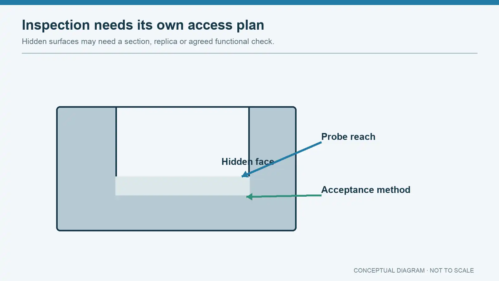
For an RFQ, send the revision-controlled model and sectioned drawing, material and state, critical undercut surfaces, allowable design changes, quantity, finish, mating component and required inspection evidence. Ask the supplier to return an access explanation covering the complete tool/holder/fixture envelope, not just a screenshot of the cutter tip. JIZAO can review the CNC geometry and proposed route against the supplied requirements; any specialist secondary process and final capability need part-specific confirmation before commitment.






