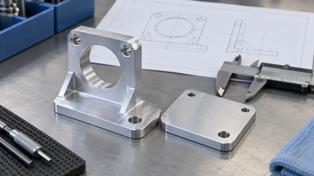
Precision should be assigned to the features that make a product locate, seal, move or assemble—not applied to every dimension on a CNC drawing. Work backward from the functional interface: define the mating condition, choose a coherent datum system, allocate size and geometric tolerances, then confirm that the machining route and inspection method can produce and verify them. This usually gives a clearer RFQ than a blanket “high precision” note, while leaving noncritical geometry room for a simpler process.
“Accurate” is not a drawing requirement
A machine's positioning specification, a quoted part tolerance and a measurement result answer different questions. Finished-part variation also depends on the stock, tool, fixture, setup sequence, thermal state and inspection method. A machine-tool calibration review hosted by NIST discusses geometric, thermal and volumetric errors and the trade-off between accuracy, complexity and cost; it does not establish a universal tolerance for every part.
Begin by naming the characteristic. A shaft diameter is a size requirement. Whether a bore is perpendicular to a mounting face is orientation. Whether a dowel hole sits in the right place relative to other interfaces is location. Flatness and surface texture are different again. A tight size tolerance on one hole does not, by itself, control its location or the flatness of the face around it.
Map each feature to the job it performs
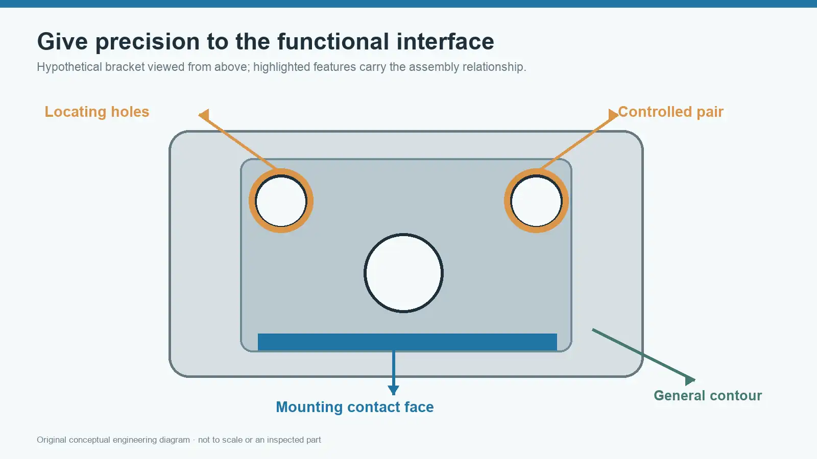
Make a functional feature map before assigning numbers. In a hypothetical sensor bracket, the mounting face sets the part against the frame; two dowel holes establish repeatable position; a clearance hole only passes a screw; and the outside contour may be non-mating. The face, dowel-hole relationship and any connector alignment may deserve stronger control than the outer silhouette. This is a design example, not a JIZAO part or production result.
| Feature role | What can fail in the assembly? | What the drawing may need | What can often remain less restrictive |
|---|---|---|---|
| Locating bore or dowel hole | Misalignment or poor repeatability | Fit and location relative to functional datums | Nearby non-mating wall thickness, if strength permits |
| Mounting face | Rocking or orientation error | Form and orientation of the actual contact area | Hidden exterior outline |
| Seal land | Leakage or uneven compression | Relevant form, texture and finished-state dimensions | Cosmetic surfaces away from the seal |
| Screw-clearance feature | Assembly interference | Clearance and accessibility | Precision location beyond assembly need |
| Visible cover edge | Appearance mismatch | Aesthetic boundary or gap requirement | Hidden internal contour |
“Less restrictive” does not mean “uncontrolled.” General dimensions still need an agreed drawing rule; the point is to spend precision where it protects function. The table cannot select a specific tolerance without the mating-part geometry, load, material and assembly method.
Allocate tolerance from the assembly backward
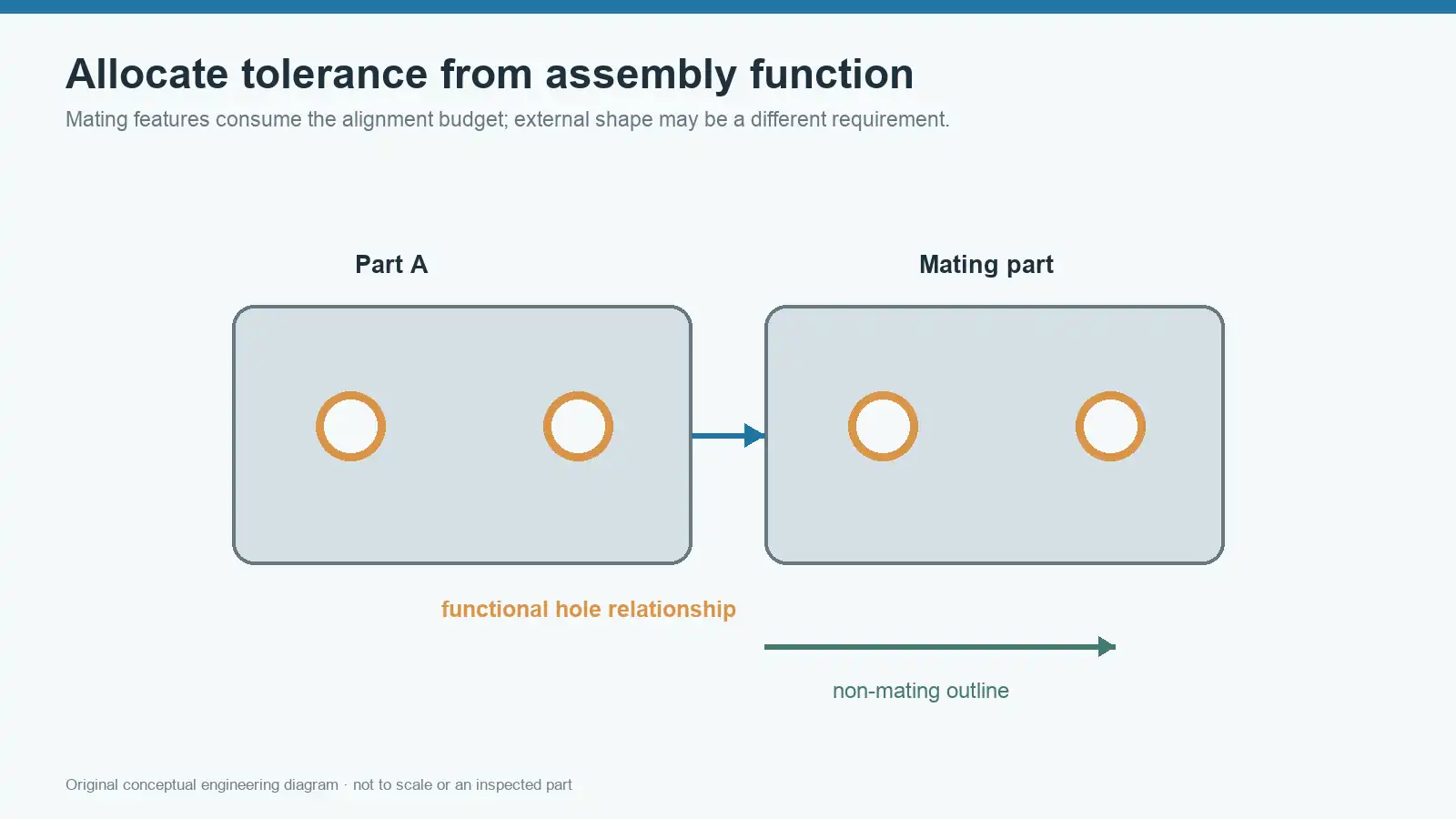
Start with the permissible assembly variation, then identify the dimensions and geometric relationships that consume it. If several components contribute to a gap or alignment, the allowable variation belongs to the stack, not automatically to one machined part. A worst-case stack can be a conservative first screen, while statistical treatment requires a justified production model and acceptance policy. Do not divide an available tolerance evenly simply because the parts are drawn in a row.
Consider a cover held by two pins. The pin diameter and mating-hole size determine fit; their locations relative to the functional mounting datums control whether the cover seats without force. Tightening a non-mating overall length may do nothing to solve that assembly problem. Conversely, loosening the pin-hole relationship to reduce quote cost can transfer cost to rework or assembly sorting. The designer should document which interface is responsible for the function, which component carries each allowance, and what happens at the limits.
Thermal expansion, finishing and operating load may change the functional condition. State whether the drawing controls an as-machined or post-finish dimension, and whether the assembly is judged at a particular reference or operating condition. ISO 1:2022 defines the standard reference-temperature framework for geometrical and dimensional specification; it does not make thermal effects disappear in service.
Choose functional datums before choosing the CNC setup
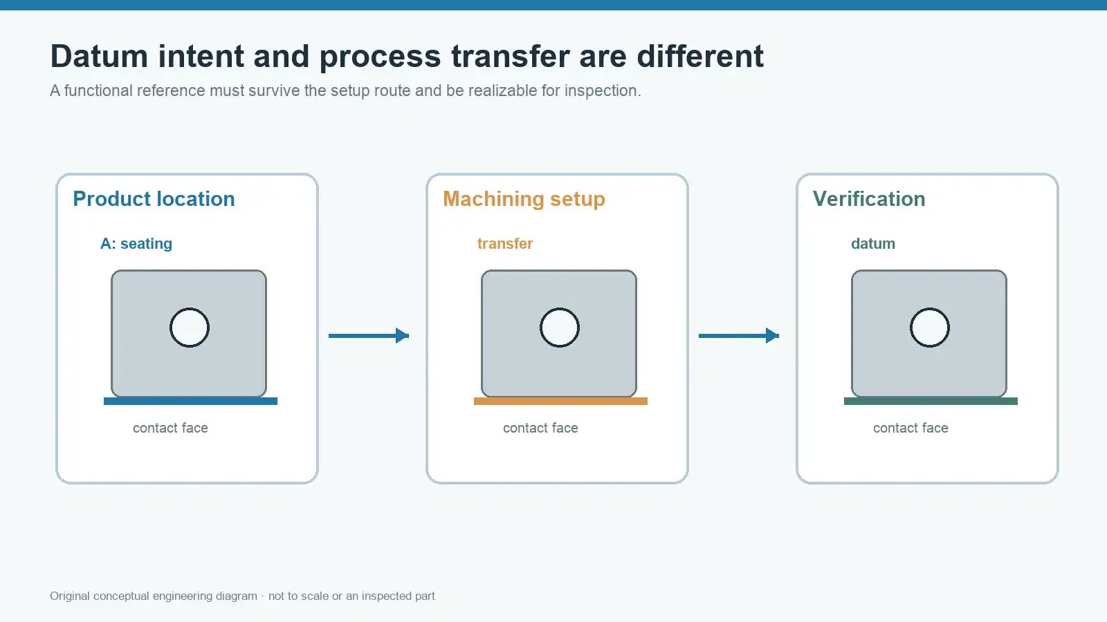
A datum reference frame (DRF) is a design and inspection reference, not a promise that the machinist will clamp on the same surfaces. Select datum features that represent how the part is actually located in the product and can be realized repeatably for verification. Then discuss how the manufacturing setup will establish or transfer that relationship. If a critical bore is on a face reached only after re-clamping, the supplier must explain how the location is preserved and checked.
The drawing's governing system matters. ASME Y14.5-2018 (R2024) is the current ASME dimensioning-and-tolerancing edition identified by ASME; ISO 1101:2017 is the current ISO GPS foundation for geometric tolerancing identified by ISO. They are not interchangeable symbol dictionaries. Use one declared interpretation framework for a particular drawing, and have a qualified engineer review any conversion between systems. This article gives no symbol-by-symbol conversion rule.
Ask how the requirement will be made and measured
The process plan should follow the controlled feature relationship. A supplier might machine related features in one setup, use a qualified transfer datum in a later setup, or adjust the design if the relationship is needlessly hard to establish. More axes can improve access for some geometries, but five-axis motion does not automatically improve every tolerance or remove the need for sound fixturing.
Inspection must be planned at the same time. A caliper may be appropriate for an accessible size, but it cannot prove a bore's position relative to a DRF. A CMM can evaluate a geometric relationship only with an appropriate datum realization, probing strategy and uncertainty; a functional gauge may be more persuasive for a specific mating condition. NIST's inspection-planning research links equipment choice to design information and measurement requirements. NIST also notes that measurement uncertainty creates acceptance risk near a specification limit. Neither a machine label nor a CMM report alone proves a stable process.
For a sensitive feature, agree which characteristic is measured, the datum setup, the instrument or gauge, sampling stage and required record. If the finish changes an interface, measure in the final condition as well as any process-control stage needed to prevent scrap. This makes the quote scope and acceptance criterion understandable to engineering, quality and purchasing.
Where unnecessary precision increases cost
A narrow tolerance can demand a more stable fixture, an extra finish operation, slower process tuning, more measurement time or a higher scrap allowance. The real cost driver is not the number of decimal places; it is the production and verification path required for the specified feature, geometry and volume. Apply a tighter requirement when a fit, seal, motion or alignment calculation justifies it. Relax it only after confirming that function and downstream assembly still work.
Three common mistakes are worth checking before RFQ:
- Blanket notes without feature logic. “All dimensions ±0.01 mm” may constrain irrelevant surfaces while failing to define bore location, flatness or finished-state acceptance.
- Datum selection by machining convenience alone. A readily clamped surface may not be the product's true locating interface. If manufacturing and design references differ, plan the transfer explicitly.
- An unmeasurable acceptance requirement. A tight profile or deep internal feature may need a specialized method; confirm access and measurement uncertainty before making it a contractual pass/fail condition.
A drawing-review package that invites useful DFM feedback
Send a revision-controlled 3D model and drawing or model-based definition, plus a short explanation of the mating components and critical characteristics. Mark the functional datum features, identify fits and finished-state dimensions, state the relevant drawing standard, and distinguish required inspection evidence from optional process data. If a tolerance is provisional, say so and ask what geometry, setup or gauge would reduce risk. For repeat production, ask how the first accepted sample becomes a controlled process rather than assuming that one conforming prototype proves capability.
A useful supplier response explains the proposed route, the characteristics that drive risk, alternatives with their functional consequences, and the method of verifying the final part. Precision is a design–manufacturing–inspection agreement, not an adjective on the RFQ.






