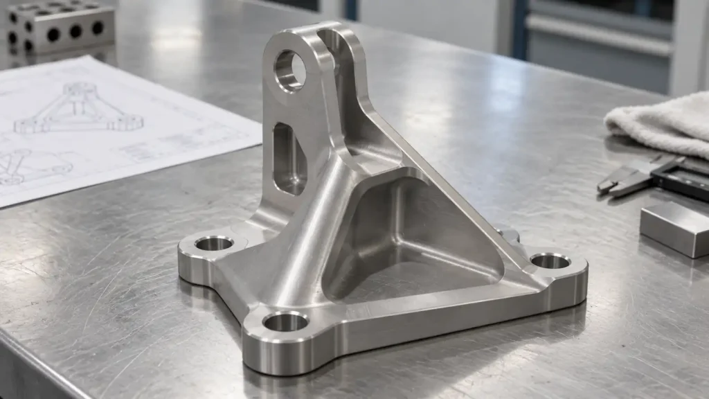
Specifying Ti-6Al-4V on an RFQ is only the start. State the product form and material condition, identify which features carry fit or fatigue-related function, and supply a drawing that distinguishes critical surfaces from ordinary stock removal. Titanium alloy machining is sensitive to the full tool–workpiece system: tool access, engagement, heat removal, chip control and part support affect the process. A supplier needs the actual geometry and acceptance plan before committing to a route or tolerance. This guide is about drawing and sourcing decisions, not a universal speed-and-feed recipe or a claim about JIZAO's titanium capability.
Identify the exact material you intend to buy
“Titanium” is not a complete purchase description. Ti-6Al-4V, its extra-low-interstitial variant, and different mill-product forms can carry different specifications and property requirements. TIMET's TIMETAL 6-4 data sheet lists Ti-6Al-4V and Ti-6Al-4V ELI separately. If the end use has a governing material standard, drawing note, approved source or traceability requirement, identify it rather than assuming a generic Grade 5 label is enough. Do not substitute an implant material specification for a nonmedical part simply because the alloy name looks similar.
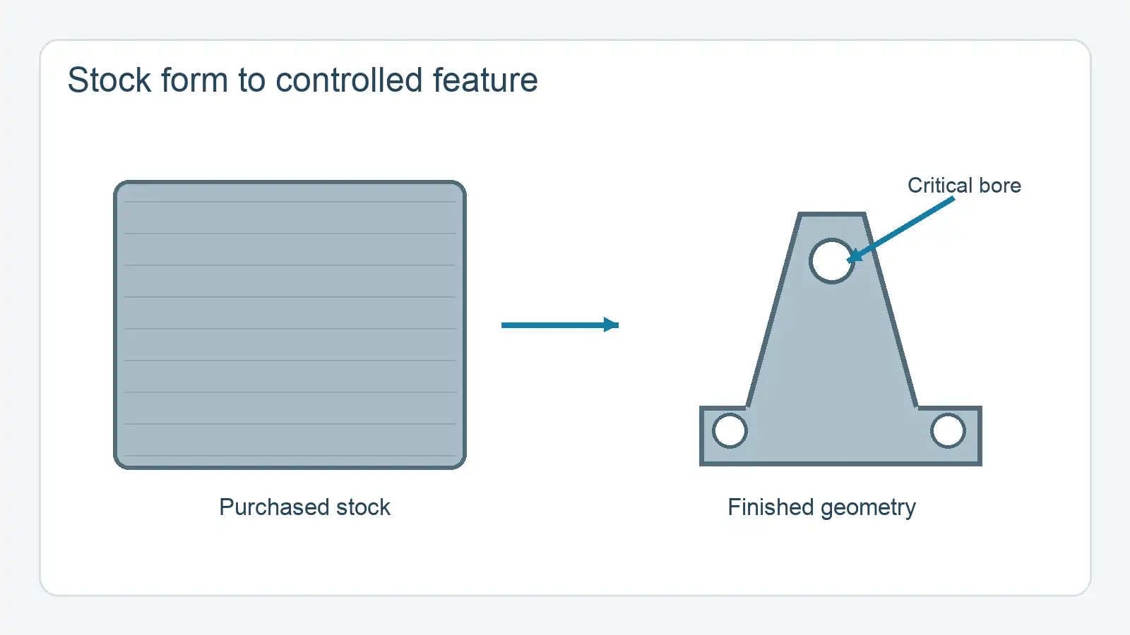
Tell the supplier whether stock is bar, plate, forging or another form; provide condition, certification and lot-traceability requirements when relevant. That information affects stock selection, available machining allowance and what the final material certificate can actually prove. The visual appearance of a silver machined part cannot verify its grade or condition. A request for a particular condition should be reconciled with the actual purchased stock and any later heat or surface process.
Why titanium changes the machining plan
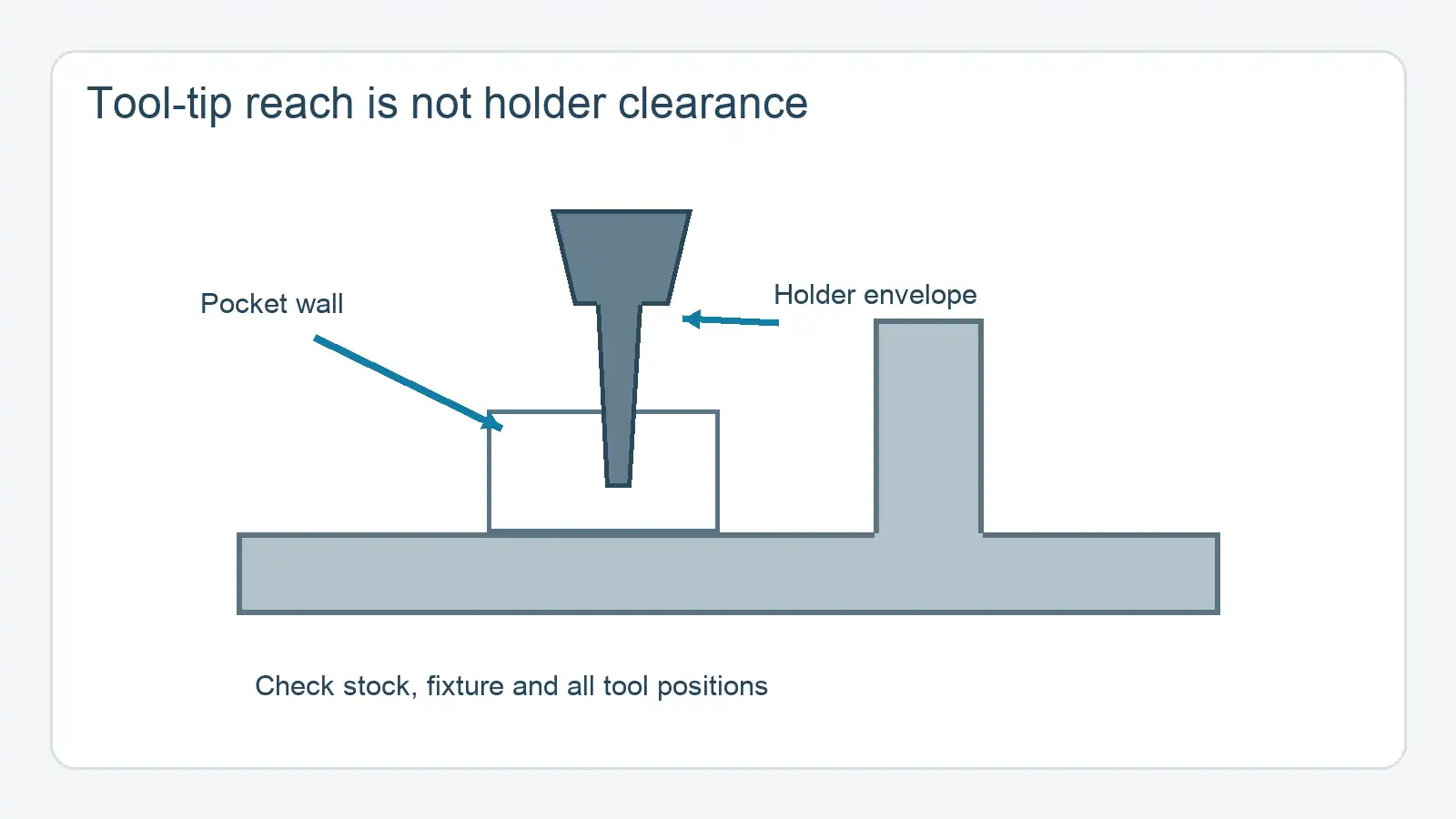
Seco's titanium machining guidance discusses heat concentration, tool wear and the need to manage tool engagement and coolant in applicable operations. The practical lesson for the designer is not to prescribe an unsupported cutting speed. It is to avoid unnecessary deep narrow cavities, inaccessible blend radii and blanket finish requirements that force long-reach tools or repeated delicate finishing. A narrow cutter held far from the spindle is less stiff than a shorter, well-supported one; if it deflects, the nominal CAD surface may not be reproduced consistently. Tool family, machine, coolant delivery, material condition and feature geometry decide the actual process window.
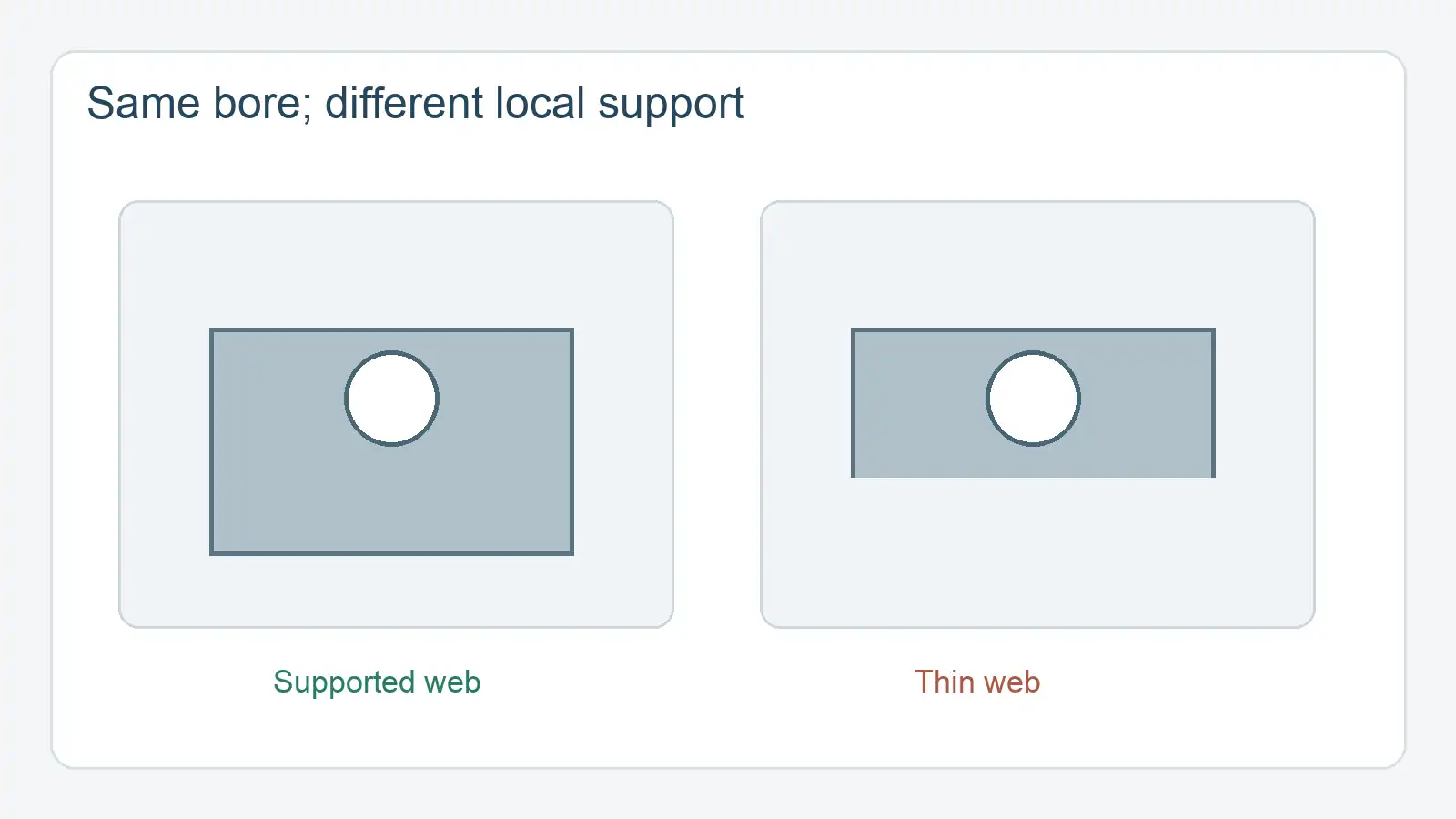
Separate roughing and finishing intent. A large volume of removed stock may justify leaving stable support for critical features until later operations. A thin flange or web can move as material is removed or clamps are released, so the drawing should state the inspection condition when a free-state fit matters. This is not unique to titanium, but expensive stock and slower, wear-sensitive cutting can make a late discovery costly. Do not assume five-axis machining eliminates such distortion; it primarily changes access and setup choices.
Put function-driven requirements on the drawing
For each mating feature, say what it must do. A locating bore may need size, form and position relative to functional datums; a fastener clearance hole may not need the same control. If a surface carries load or fatigue sensitivity, its edge condition, transitions and damage limits may matter more than a cosmetic polish instruction. Define inaccessible corners and allowed tool radii where a long cutter would otherwise be required. Avoid copying one tight plus/minus value across every pocket and profile.
For a multi-face bracket, identify the datum reference frame used for acceptance and the surfaces available for safe clamping. A machining fixture may touch sacrificial stock or nonfunctional pads while the final CMM setup uses the drawing's datums. Keeping these separate prevents an apparently convenient fixture origin from silently becoming an inspection requirement. A change of setup can affect feature-to-feature relationships, so call out only the relationships needed in assembly and agree how they will be measured. Do not use an ASME or ISO GD&T symbol in a released drawing without identifying the applicable drawing system and reviewing the actual requirement.
Surface texture should also follow function. A bearing, seal, bonded or fatigue-sensitive interface may justify a defined process and inspection method; a hidden clearance pocket may not. “Smooth all over” is not a measurable finish plan. If a later coating, passivation or other surface treatment is required, specify the final-state geometry and any masked interfaces separately. The treatment provider and part designer should verify compatibility with the selected alloy, application and inspection plan.
Decide where five-axis access helps—and where it does not
Five-axis or indexed 3+2 positioning can shorten a tool or reach a face that would otherwise require another fixture. That can be useful for a bracket with angled pads and deep blends. It does not automatically reduce cycle time, improve every tolerance or remove a need for a stable base setup. Ask a supplier to evaluate the holder, spindle, clamps and stock through the full toolpath, including roughing stock. If a simpler setup can produce the same critical relationships and is easier to inspect, it may be the better route.
Plan verification and quote scope together
Put a realistic acceptance method next to critical geometry before placing an order. CMM access can be limited by a deep pocket or narrow angle, while a simple gauge may verify fit but not profile or datum location. Ask which characteristics will be checked on the free part, which require a fixture, and which need a post-treatment inspection. Measurement capability is separate from machine capability. A first article may expose reach or measurement problems, but it cannot substitute for an agreed production sampling and change-control plan.
For an actionable RFQ, send the released 2D drawing and 3D model, exact alloy/condition and stock form, required certificates, quantity and batch pattern, critical functional interfaces, finish state, special edge rules, and inspection/documentation requirements. Mark approved design flexibility, such as a radius or pocket-depth change, so the supplier can propose a safer tool-access plan without guessing which geometry is immutable. Ask for explicit exceptions to tool access, process, material sourcing and measurement; avoid interpreting a quote as blanket confirmation of unspecified capabilities.
Bottom line: a Ti-6Al-4V part should be sourced as a defined material, geometry and verification problem. The best machining strategy depends on the actual feature layout and conditions, not the alloy name or the machine-axis count alone.
For a part-specific review, use the CNC machining service overview to frame the process questions, then send the drawing and RFQ requirements for an engineering assessment. Do not send controlled information until the intended disclosure route is agreed.
FAQ
Is Ti-6Al-4V ELI interchangeable with ordinary Ti-6Al-4V?
Do not assume so. Use the material specification and design authority's approved substitution rule for the application; the variants are separately documented by the producer.
Does a five-axis machine guarantee a better titanium part?
No. It can improve access and sometimes reduce setups, but tool wear, heat, workholding, programming and inspection still control the result.
What should a buyer clarify first?
Confirm material form/condition, the few interfaces that truly require tight control, finish state and evidence required for acceptance. Those answers make a manufacturing review and quote much more useful.






