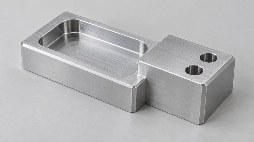
Start CNC troubleshooting by describing the defect, checking the measurement, and preserving the production history—not by choosing a favorite cause. Dimensional drift, vibration marks, ordinary tool marks, burrs and overcut can share contributing factors, but they require different checks. A useful investigation connects the affected feature to its tool, program, setup and inspection method, then tests a bounded explanation before changing the production process.
This guide focuses on milled metal components, with drilled-hole exits where relevant. It helps product engineers and buyers ask for evidence; it is not a feed-and-speed prescription or a diagnosis of a particular factory’s parts.
First classify the problem and contain the risk
If a result threatens a functional requirement, have the responsible manufacturing and quality team contain the potentially affected parts and decide whether the operation must stop. Keep the last known conforming result and the first suspect result identifiable. Do not polish away the surface, discard the cutting tool or reset all offsets before recording the evidence.
Describe where, when and how the change appeared. Is one wall wrong, or are several features displaced together? Does the condition develop with successive parts, repeat at the same toolpath corner, or appear after reclamping? A scaled close-up is useful, but a photograph alone cannot verify a dimensional tolerance or a surface-texture requirement.
| Observation | Explanations to investigate | Evidence that helps separate them |
|---|---|---|
| Size moves gradually in one direction | Edge wear, thermal change, compensation history, measurement change | Sequential results linked to tool usage, temperatures and offset events |
| Repeated waves or vibration marks | Cutting-system instability, periodic forcing, variable engagement, support weakness | Exact cut location, tool assembly, cutting conditions and suitable vibration data |
| Regular cutter tracks or isolated scratches | Expected cutting geometry, runout, damaged edge, chip recutting, pass transitions | Same-scale surface comparison, tool inspection and path review |
| Raised material at an edge or hole exit | Edge preparation or wear, material behavior, exit conditions and support | Identified edge, pre/post-deburr condition and exit-side access |
| A local gouge or missing intended material | Path, offsets, tool definition, part movement or load-dependent deflection | Controlled NC revision, setup records and measured deviation from design |
These are competing explanations, not a lookup table of certain diagnoses. First rule out unreliable evidence; then follow the branch most consistent with the feature and its history.
Dimensional drift: separate cutting change from measurement change
Dimensional drift is a changing measurement over the run, rather than simply one dimension being wrong. Record the results in production order before sorting them into a pass/fail summary. Preserve measurement conditions and the actual compensation events: a series measured after different waiting times or with changing alignment may not represent one comparable trend.
Temperature affects both the object and the measurement system. NIST’s thermal-expansion study develops this measurement relationship rather than treating temperature as a machine-only issue. Recheck the same feature using an agreed method and thermal condition. Confirm clean contact surfaces, instrument suitability, datum alignment and repeatability before adding an offset to chase a suspect result.
On the machining side, changing edge condition can change cutting behavior, while thermal change can affect position feedback. Renishaw’s encoder-scale explanation shows how scale expansion and mounting influence reported position. The actual machine architecture matters. Neither wear nor thermal change has one universal sign in a finished-size result: direction depends on the feature, cutting side, compensation and measurement conditions.
Ask whether the trend follows accumulated tool use, time from startup, a material lot, an offset edit or a new setup. A measured step immediately after an edit deserves a different investigation from gradual movement between edits. That comparison narrows the cause tree; it does not prove a cause by correlation alone.
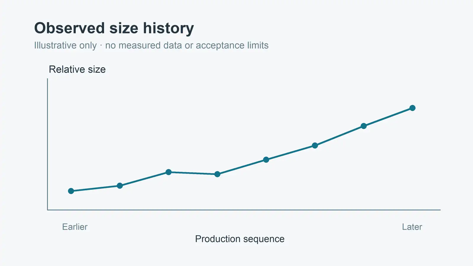
For a recurring order, ask the supplier to define when results trigger review, who may change compensation, and how the change is recorded. A correct-looking value after an undocumented offset is not evidence that the underlying process has become stable.
Chatter and regular tool marks are not the same diagnosis
In machining dynamics, chatter usually means self-excited vibration: interaction between the cut and the structure sustains the oscillation. In regenerative chatter, a cutting edge encounters waviness left by a previous engagement, changing chip thickness and the next cutting force. Periodic forcing can also produce vibration-related surface patterns. The milling chatter-detection review distinguishes these mechanisms and discusses signal-based classification. Appearance and sound are clues, not sufficient proof of regenerative chatter.
Normal cutter tracks can remain visible on an otherwise acceptable surface. Isolated scratches, smeared areas or marks at a pass boundary are different observations again. Compare the location and spacing with the programmed passes and examine the cutting edge, tool assembly and chip evacuation. For functional surfaces, check the specified texture and geometry separately: an attractive surface does not establish correct size, and correct size does not establish acceptable texture.
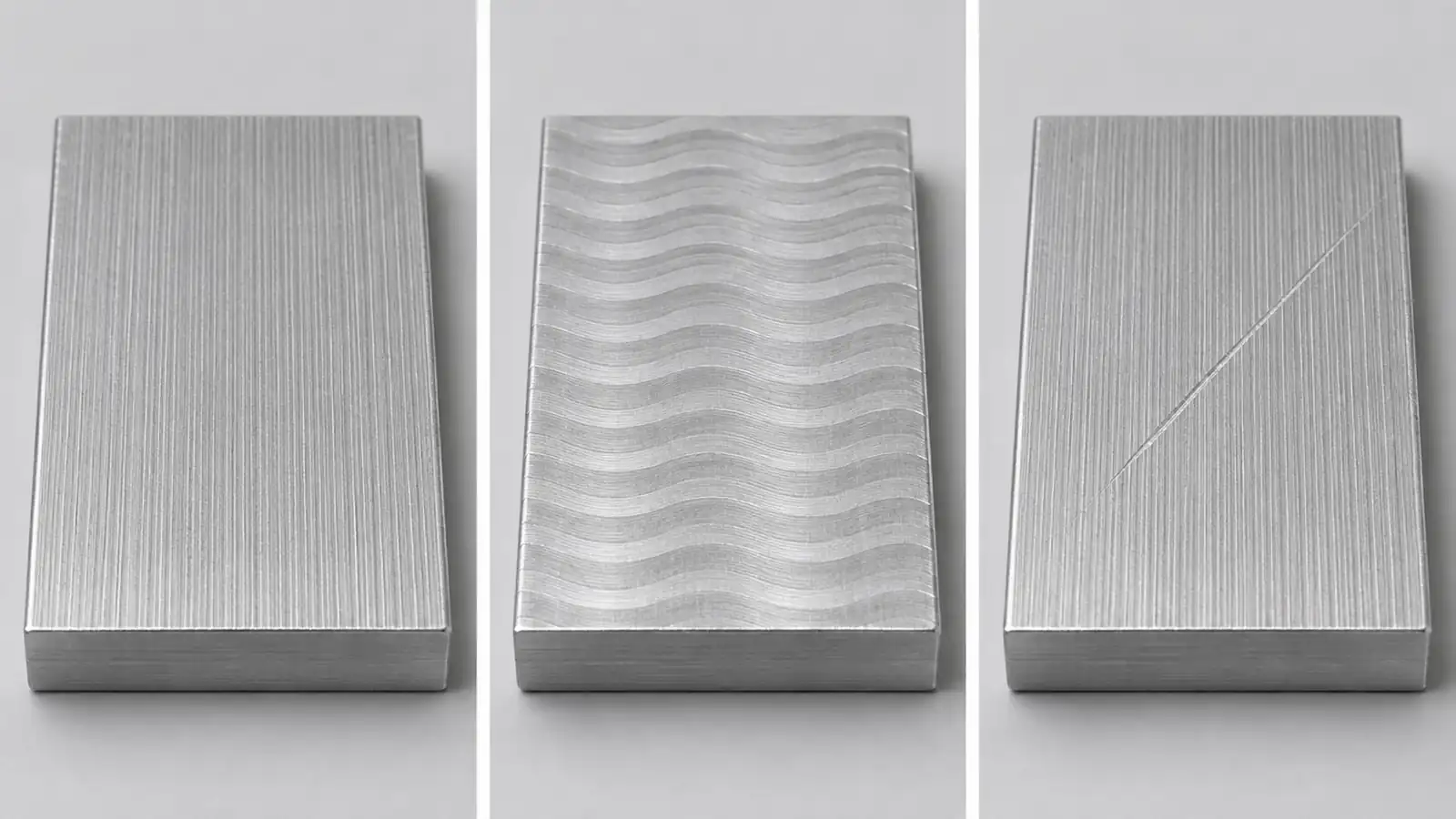
Stability belongs to the complete cutting system. A long tool assembly, weakly supported wall or abrupt rise in cutter engagement can change the response. Haas’s milling troubleshooting guide treats wear, overhang, engagement, toolpath and coolant as separate contributors. Review these conditions together, especially where a pocket corner or a deeper wall changes the load.
A new tool may temporarily improve the cut because the edge condition and cutting forces have changed. If the marks return, that does not exclude the tool; progressive wear may be exposing a marginal setup. Likewise, “reduce the feed” is not a universal remedy. The same Haas guide identifies excessively light chip loading as another possible contributor. Any parameter trial must remain within tool/material guidance and approved machine limits, with the resulting feature checked—not merely the noise.
For a buyer, the useful question is: what condition changed, what evidence supports the proposed mechanism, and did the correction preserve the required surface and geometry? Asking for a higher-axis machine alone does not answer it. Five-axis access may allow a shorter assembly for some features, but does not automatically resolve vibration.
Burrs: investigate formation without treating deburring as failure
A burr is unwanted material remaining at an edge. At a drilled exit, the remaining material can deform as the cutting edge breaks through; material behavior, edge geometry and exit loading change that response. Mitsubishi’s drilling troubleshooting guidance identifies edge honing and exit feed as application-dependent factors. Do not transfer one drill’s remedy to every milling edge or alloy.
Also review the exit-side support and cutting direction or sequence. An experimental drilling study investigated backing support in low-alloy steel. It supports considering support as a variable—not promising a universal burr reduction for aluminum. A backing arrangement must fit the actual geometry, clamping, chip clearance and tool travel.
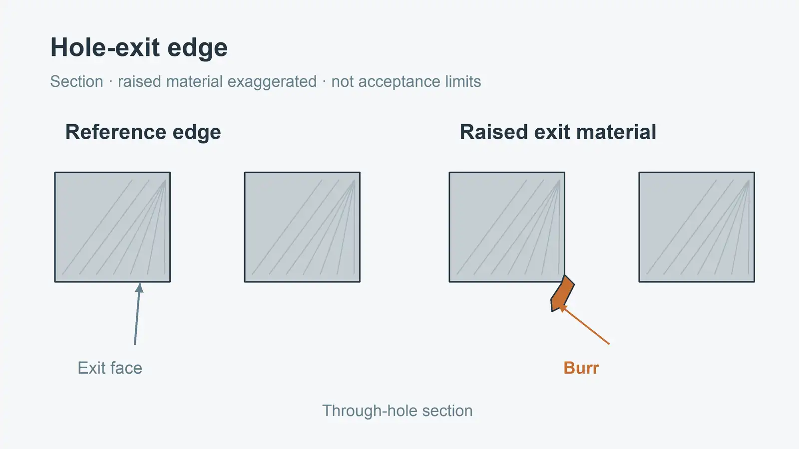
Deburring can be a planned, necessary operation. The issue is an uncontrolled edge condition, inaccessible unwanted material, loose contamination or secondary damage to a protected feature—not the existence of a deburring step. Check the edge before and after that operation. A removed burr is not a successful correction if the process also enlarges a locating hole or rounds a sealing boundary beyond its requirement.
For repeat supply, separate formation control from final acceptance. Investigate a change in burr behavior against tool condition and process history, while verifying the finished edge against the agreed requirement. Use the edge-requirement guide to specify protected edges and defined transitions rather than inventing a universal allowable burr size.
Overcut: locate the missing material before assigning disposition
Here, overcut means removing material beyond the intended finished boundary. First distinguish it from a surface mark or an incompletely removed allowance. Map the affected area to the design and measure the relevant depth, profile or feature relationship using a method suitable for that requirement.
Review the controlled model, CAM setup, posted NC program, tool geometry, tool-length and radius compensation, work coordinates, fixture orientation and actual seating. A physical shift or load-dependent tool/part deflection is a separate branch from a programmed path error. Do not assume that the sign of deflection always leaves extra stock; direction and engagement matter.
Simulation helps test the digital branch. Autodesk documents different checks with and without a machine model, including rapid-motion cuts into stock. Vericut’s design-versus-cut-stock comparison can identify gouges and excess material, subject to its comparison settings and cutting resolution. Check the appropriate posted-program/machine configuration rather than treating a visually clear CAM animation as proof of safe physical production. Digital verification cannot establish that the real part stayed seated or that the entered offsets matched the model.
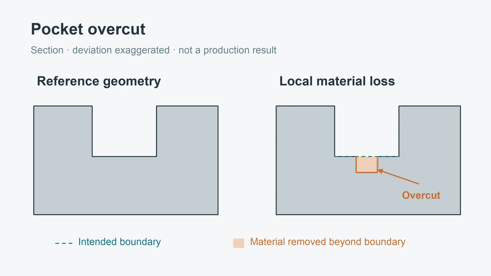
Further cutting cannot restore the material already removed. But that does not make every affected part automatically scrap. The drawing owner and authorized quality/design authority must decide whether an approved rework, repair, concession or rejection is appropriate for the actual function and deviation. Keep suspect parts identified and do not silently blend out a gouge on a critical surface.
Close the loop rather than repeat the temporary fix
A correction changes the immediate condition; root-cause closure explains why it occurred and why the revised control should prevent recurrence. Where safe and practical, change a bounded factor and document the result. When several interacting factors require a designed trial, record the combinations rather than attributing improvement to whichever change happened last.
Keep the following controls connected to the affected feature:
- Tool life: replacement criteria based on the observed tool/process behavior, not an invented universal part count.
- Program control: identifiable model, CAM, post and NC revisions, with approved changes traceable to the run.
- Fixture condition: clean locating interfaces, verified seating and checks of relevant wear or support.
- Compensation: named authority, reason, limit and recheck requirement for each adjustment.
- Trend review: sequential measurements linked to tool, setup, thermal state and intervention events.
NIST’s control-chart guidance explains that greater sensitivity to trends can increase false alarms. Choose monitoring rules appropriate to the data and process; do not confuse a drawing’s specification limits with statistically derived control limits. A trend signal prompts investigation, not an automatic diagnosis of tool wear.
Finally, verify the revised process beyond one attractive sample: check the affected feature and related requirements over the agreed production conditions, including relevant tool-life and setup changes. A machine positioning specification, a passing part and a capable inspection method are three different kinds of evidence. None substitutes for a demonstrated repeatable process.
What to prepare for a supplier review
Begin with non-confidential problem context: affected feature and function, material/condition, operation, observation pattern, last known conforming point and proposed acceptance checks. Ask the supplier to explain its cause tree, planned evidence checks and validation—not simply to promise “better quality.”
For complex multi-face parts, a five-axis process review can examine access, tool length and setup relationships alongside the defect investigation. Contact JIZAO about the review and confirm an approved secure exchange route before sending confidential drawings, programs or reports. Process changes and part disposition remain subject to engineering and quality approval.






