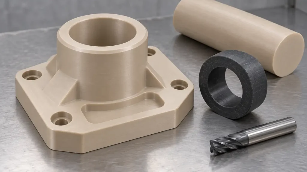
The featured visual is an AI-generated engineering concept, not a customer component, production photograph or inspection record.
PEEK can produce stiff, chemically resistant precision components, but “PEEK” alone is not a complete material specification. Unfilled, glass-filled, carbon-filled, bearing, medical and other application-specific grades can behave differently in cutting, clamping, deburring and inspection. A reliable CNC plan begins with the exact grade and stock form, then manages heat, residual stress and restraint around the part’s functional requirements.
This guide is for product engineers and buyers preparing a machined PEEK part for quotation or release. It does not provide a universal feed-and-speed recipe: tool geometry, grade, feature size, setup rigidity and stock history can change the safe process window.
Specify the PEEK grade, not only the polymer family
PEEK is a polymer family, not one interchangeable material. Even unfilled grades can differ in molecular weight, flow behavior and property balance. Reinforcement and fillers create larger differences.
| Material description | What may change in machining | Drawing and RFQ implication |
|---|---|---|
| Unfilled PEEK | More ductile cutting response; burr formation and local heat still require control | State the manufacturer, grade and color if substitution is not acceptable |
| Glass-fiber reinforced PEEK | Higher stiffness, different anisotropy and abrasive wear behavior | Identify the exact compound and any orientation-sensitive functional surfaces |
| Carbon-fiber reinforced PEEK | Higher stiffness and conductivity than an unfilled grade, with abrasive reinforcement | Confirm tool strategy, edge condition and whether electrical behavior matters |
| Bearing or wear grade | Lubricating fillers may change friction, color and mechanical behavior | Specify the approved grade rather than asking the shop to infer it from “bearing PEEK” |
| Medical, food-contact or semiconductor grade | Traceability, cleanliness and change control may dominate the route | Send the applicable specification and documentation requirements with the RFQ |
Victrex, for example, identifies 450G as one specific natural-colored general-purpose PEEK grade and explains that different molecular weight changes stiffness, strength, toughness, crystallinity and processing behavior. That manufacturer-specific information is useful evidence of why a grade suffix matters; it is not a blanket specification for all PEEK stock.
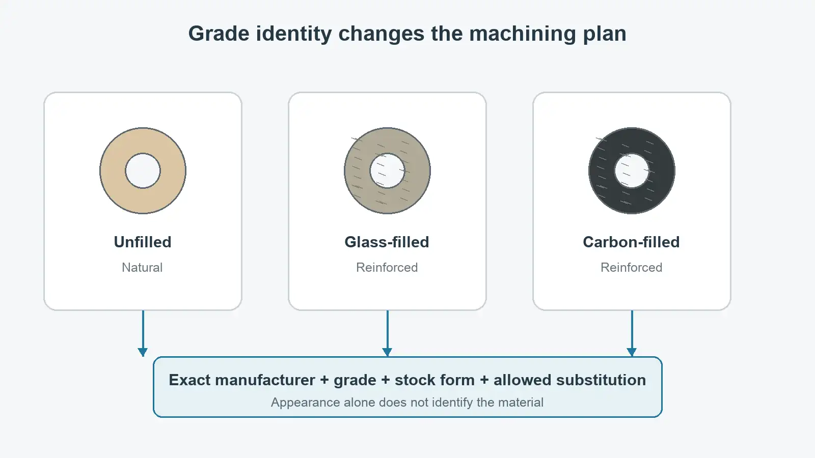
Do not permit an apparently similar black or beige stock to be substituted by appearance. Color cannot establish reinforcement, filler system, resin source, compliance status or processing history. If equivalence is allowed, define who approves it and which property and documentation requirements must be demonstrated.
Moisture and thermal history are different questions
PEEK is often described as having relatively low moisture uptake compared with some engineering polymers, but “low” does not mean that conditioning can be ignored. The material supplier’s data, the application environment and the required measurement uncertainty should determine whether drying or conditioning is relevant. Pellet-drying instructions for molding are not automatically a machining procedure for finished stock shapes.
For machined parts, thermal history is usually the more direct dimensional concern. Extrusion, compression molding, injection molding, annealing and previous machining can leave different stress and crystallinity conditions. Removing material from only one side of a plate or from the inside of a thick ring can unbalance those stresses and allow the part to move.
Annealing can reduce residual stress in suitable stock or between machining stages, but it is not a universal corrective step. The cycle must match the exact grade, stock supplier, section thickness and final property requirements. Temperature, hold time and cooling rate copied from another resin or another stock form can change crystallinity, dimensions or ductility rather than improve the part. Obtain the stock manufacturer’s instructions and document when the condition matters.
Control cutting heat without treating PEEK like metal
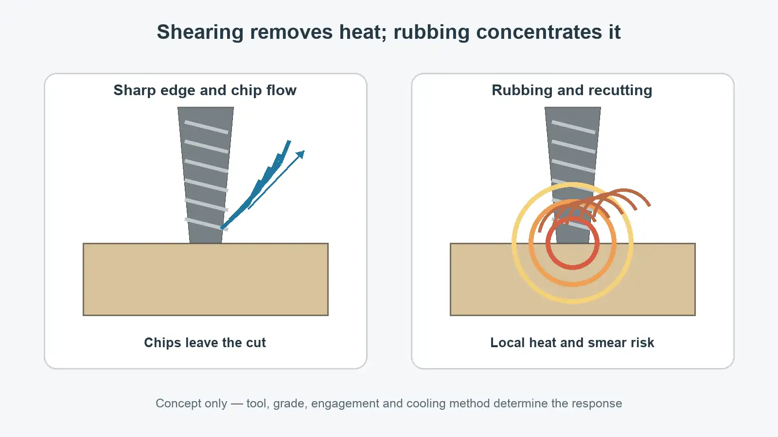
Cutting heat enters the tool, chip and workpiece. In PEEK, local heating can soften the cut zone, smear an edge or change how a thin feature responds under force. At the same time, aggressive external cooling or a poorly chosen fluid can introduce contamination, compatibility or thermal-shock concerns for a controlled application.
The process response is therefore conditional:
- use sharp, suitable cutting edges so the tool shears rather than rubs;
- keep chips leaving the cutting zone instead of recutting them;
- choose tool engagement and feed that avoid prolonged rubbing;
- limit unnecessary tool overhang and runout;
- apply air, coolant or another cooling approach only after checking material, cleanliness and downstream requirements;
- monitor tool condition, especially with abrasive reinforced grades.
Published cutting tables are starting references tied to a tool family, grade, operation and setup. They do not prove that a thin PEEK wall, a deep bore or a reinforced grade can use the same spindle speed and feed. A trial plan should define what will be observed—chip form, edge quality, surface condition, tool wear and dimensional movement—before a parameter is released for repeat production.
Stock selection and roughing strategy affect dimensional stability
Choose stock with enough machining allowance, but do not assume that more excess is always safer. A large buy-to-fly ratio adds time, heat and material waste. It can also require deep stress-releasing cuts before the final geometry exists.
For distortion-sensitive parts, a staged route can be more stable than finishing every feature immediately:
- Establish traceable material identity and inspect the incoming stock condition.
- Rough the major material volumes while keeping balanced allowance where geometry permits.
- Release and re-establish restraint before assuming the part is stable.
- Apply an approved stress-relief or conditioning step only if the material route requires it.
- Finish functional features from a datum strategy that matches the drawing.
- Allow the part to reach the defined inspection condition before final acceptance.
This sequence is a planning model, not a mandatory recipe. A small symmetric spacer may not need the same route as a thin split ring or a large pocketed plate. The controlling variables are stock form, section changes, removed volume, required tolerance, batch size and how the part is held.
Workholding must resist motion without printing the fixture into the part
PEEK’s stiffness and local contact response differ from metal. High point loads can indent a surface or distort a thin ring while it is clamped. If the feature is inspected before the part has recovered from restraint, the reading may describe the fixture state rather than the free part.
Good fixture planning spreads load, supports the cutting-force path and preserves access to the features that establish the datum system. Soft jaws, full-contact nests, sacrificial supports or multiple light clamps may be appropriate, but each can also hide a surface, trap chips or over-constrain the part. The drawing should make clear whether a dimension applies in the free state, assembled state or another controlled condition.
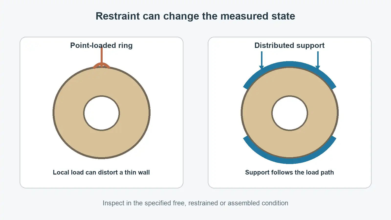
Thin walls, interrupted rings and long slender features deserve an explicit unclamped inspection check. If a mating component defines the functional state, supply the interface and assembly information rather than expecting the machinist to infer it.
Burrs and edges need functional language
A generic “deburr all edges” note does not define an acceptable PEEK edge. A knife edge may feather; a drilled exit may form a lip; reinforced material may leave a different edge than an unfilled grade. Manual scraping or tumbling can change a sealing land or small hole even when the edge looks cleaner.
Identify the edges that affect assembly, sealing, flow, electrical isolation or handling. Where an edge break is required, define its extent and whether a radius or chamfer is functionally preferred. Where material must not be removed, protect that surface explicitly. Visual acceptance samples can help with cosmetic expectations, but they do not replace a dimensional requirement.
Inspection must match the polymer and the feature
Measurement force, support, temperature and elapsed time after unclamping can all affect a PEEK reading. A heavy contact force that is harmless on a steel block may deform a thin polymer wall. A CMM can measure complex relationships, but it does not make an unstable datum, unsuitable fixturing or excessive probing force valid.
Plan inspection around the characteristic:
- use low and controlled contact force where deformation is plausible;
- support the part consistently without forcing it into the nominal shape;
- record the relevant free, restrained or assembled condition;
- identify temperature or conditioning requirements when they affect acceptance;
- define sampling and documentation for production rather than extrapolating from one prototype;
- separate surface texture, size tolerance and GD&T—they are different requirements.
For very tight or temperature-sensitive requirements, the drawing owner and supplier should agree how the characteristic will be verified before quoting it as routine. A machine’s positioning specification is not evidence that the complete machining and inspection process can repeatedly accept the finished polymer feature.
What to put on the drawing and send with the RFQ
At minimum, provide:
- exact resin/compound manufacturer and grade, plus allowed substitutions;
- stock form and any required material certificate, lot traceability or regulatory documentation;
- color and filler or reinforcement requirement;
- controlled CAD model and PDF drawing with revision status;
- functional datums, fits, size tolerances and GD&T rather than a universal tight tolerance;
- surface-texture requirements only on surfaces where function needs them;
- edge-break, burr and cleanliness requirements;
- free-state, assembled-state or restrained-state acceptance conditions;
- operating temperature, chemical exposure and mating materials when relevant to material selection;
- prototype quantity, expected production quantity and required inspection records.
Also identify whether supplied stock must be used, whether re-annealing is prohibited or required by a controlled specification, and whether coolant or cleaning agents are restricted. These fields let the supplier develop a conditional process instead of guessing from “machine PEEK per model.”
Review the material, geometry and acceptance method together
PEEK machining succeeds when the material identity, stock history, geometry, workholding, heat control and inspection state agree. Grade selection cannot be separated from the drawing, and a low nominal roughness or tight size tolerance cannot compensate for an ambiguous material or acceptance condition.
For a new part, send the controlled model, drawing and exact material specification for a DFM review. JIZAO can review tool access, workholding and inspection questions for the proposed component, but manufacturability and any achievable requirement remain subject to the actual grade, geometry, quantity and verification plan. See our five-axis machining service for multi-face access context, our STEP and PDF drawing guide for the document package, or contact JIZAO to discuss a non-confidential drawing.






