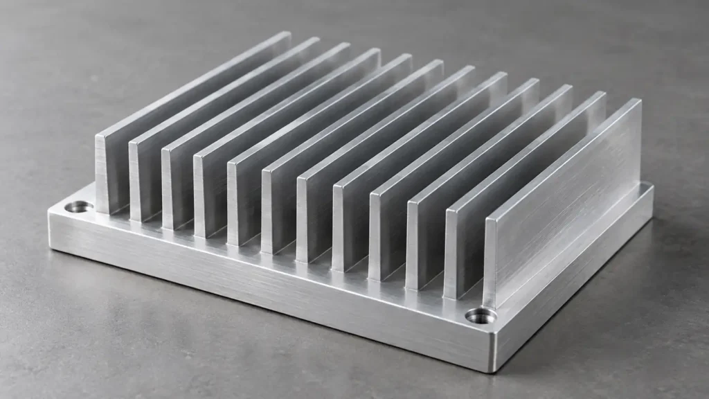
An aluminum heat sink is not defined by its fin count alone. For a CNC-machined design, the buyer and machinist need the thermal boundary conditions, the base-to-device interface, the airflow direction, the mounting scheme, and the features that actually require inspection. A dense fin pattern can add cost without improving cooling if air cannot move through it. A nominally flat base can also perform poorly if the assembled interface, thermal interface material (TIM), and contact pressure are not considered together. This guide turns those dependencies into a practical drawing and RFQ checklist. It is general engineering guidance, not a JIZAO test result or a guaranteed thermal rating.
Start with the heat path, not a fin sketch
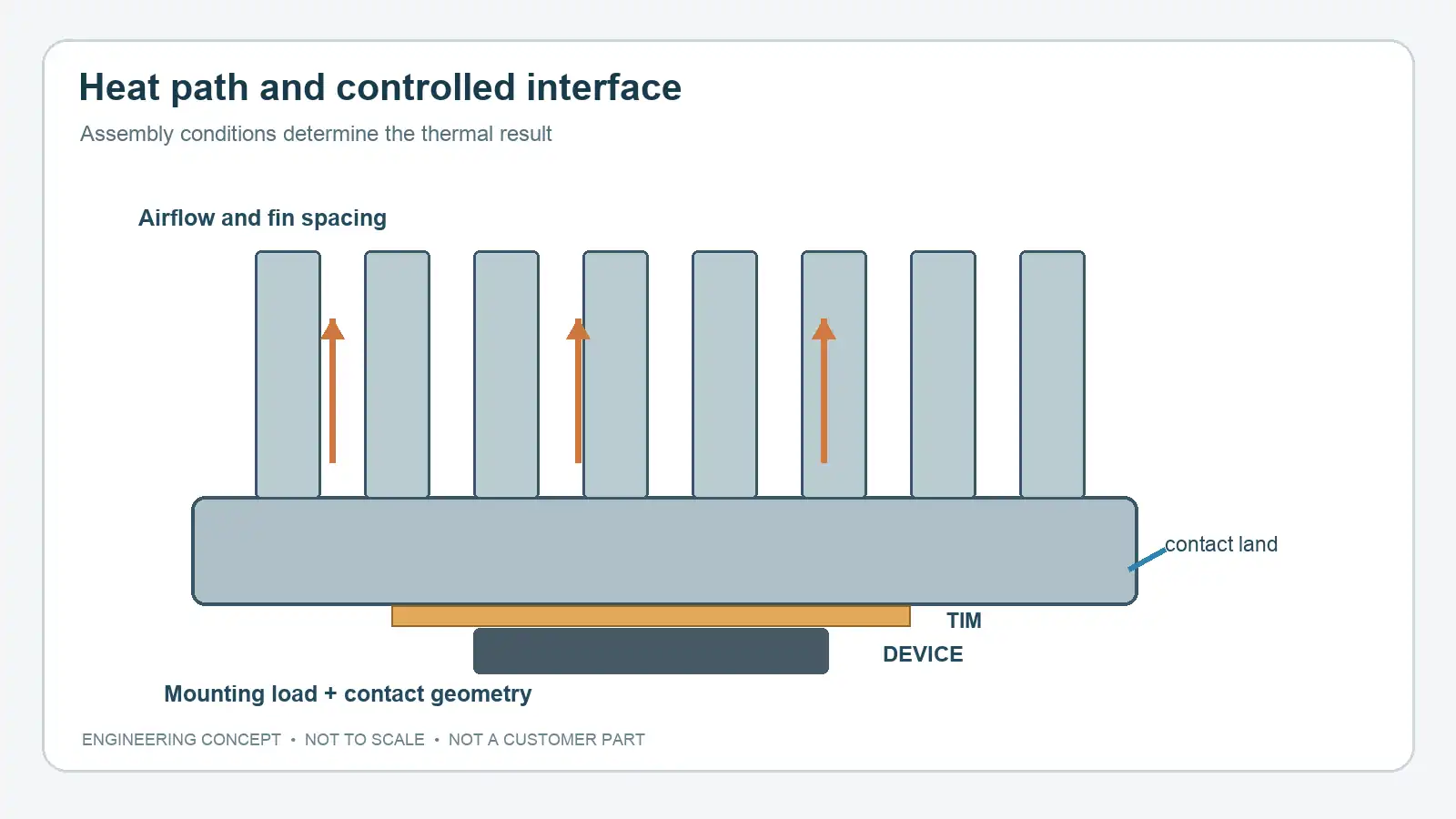
The heat path runs from the device through its package and TIM, into the heat-sink base, through the fins, and finally to the surrounding air. Each link has a resistance. A lower-resistance fin geometry cannot compensate for an unexamined device-to-base interface. Before quoting a machined heat sink, provide heat dissipation, allowable device or base temperature, ambient temperature range, available envelope, orientation, and whether cooling is natural or forced. If a fan is involved, identify the airflow direction and the fan/system operating condition rather than only its free-air rating. Thermal simulation or physical testing should use the assembled condition, not the bare metal part alone. Boyd's heat-sink selection guidance and Henkel's TIM guide both treat flow conditions and interface performance as design inputs, not decoration. [1][2]
Which surfaces belong on the controlled drawing?
Mark the device-contact land explicitly. Specify its usable area, position relative to mounting features, and the functional flatness/finish requirement justified by the interface design. The TIM supplier's application guidance, compression or bond-line targets, and hardware loading matter; do not assume a generic roughness number improves every interface. If the base receives anodizing or another coating, say whether the contact land must remain bare or is evaluated in the coated state. Define the inspection state—before or after finishing—so the shop and inspector do not measure different versions of the same requirement. [2]
Choose fins around airflow and manufacturability
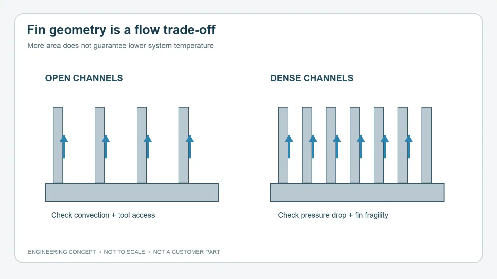
Fin height, thickness, pitch, length, and orientation interact. Closer fins raise nominal area, but can obstruct natural convection or increase pressure drop in a forced-air system. The best spacing depends on flow and package constraints; it is not a universal ratio. Boyd's selection guide ties fin density and geometry to air velocity and fin length, while Advanced Thermal Solutions explains why very close spacing may reduce natural-convection performance. Use those sources as design context, then validate the final geometry for the actual enclosure and operating point. [1][3]
CNC machining is useful for prototypes, low-volume variants, integrated mounting geometry, and features that an extrusion cannot readily provide. It does not make every tall, thin fin economical or robust. Long narrow slots require tool reach and chip evacuation, and fragile fins can deflect or be damaged during handling. If the design is likely to scale, compare a machined prototype with an extrusion, bonded/skived assembly, or other production route while holding the thermal and mounting interfaces constant. That is a process-selection conversation, not a promise that one route is always cheaper. [4]
Put function before blanket tolerances
Separate requirements into three groups. First, the thermal interface: contact-land geometry, finish, coating state, and the relationship to the device. Second, assembly: mounting-hole size and pattern, thread callouts, clearance for fasteners, and overall envelope. Third, airflow geometry: fin pitch, minimum gap, height, and features that must clear a duct or fan. A general profile tolerance on every fin face can make a quote hard to interpret without improving the heat path. Conversely, a contact land specified only as an overall part thickness may leave its assembled relation uncontrolled.
Ask how each critical feature will be measured. A broad contact land may be checked by a method different from a deep fin gap; the drawing should distinguish accessible datum/contact surfaces from nominal CAD surfaces. If a coating or conversion treatment is required, state the standard/finish, target appearance only when functionally relevant, masked areas, and whether the final dimensions apply after finishing. Do not silently assume a coating thickness or dimensional compensation: confirm it with the selected finisher and the application specification.
A concise RFQ package
Send a revision-controlled drawing and 3D model, then add the conditions that a geometric file cannot convey:
- Heat load, ambient range, permitted temperature, enclosure orientation, and natural or forced airflow; include airflow direction and system restrictions.
- Device footprint, TIM type or selection status, contact-land requirement, mounting preload or hardware concept, and bare/coated contact state.
- Candidate alloy/temper, finish, cosmetic zones, electrical grounding or isolation needs, and any masked areas. If the alloy is open, say so.
- Prototype and forecast quantities, test plan, and which dimensions are critical-to-function after finishing.
- Acceptance and inspection method for the contact land, mounting pattern, and minimum fin clearance.
These inputs allow a supplier to flag a tool-access issue, propose an alternate fin route, or identify a missing test boundary before it becomes a nonconformance. An RFQ should not convert an untested thermal estimate into an acceptance criterion. If thermal performance is contractual, define the assembled test fixture, power, ambient, airflow, sensor positions, and pass/fail method separately from the part drawing.
Example decision: dense fins versus a serviceable interface
Imagine two CAD concepts with the same outside envelope. One adds more tall fins, but narrows the channels and leaves little tool clearance. The other has fewer accessible fins and a clearly specified contact land, mounting pattern, and fan-flow direction. The second is not automatically cooler. It is, however, easier to quote and test because its unknowns are explicit. The engineering next step is to compare both at the actual flow condition and assembled TIM state, then freeze only the geometry shown to deliver the required result. This is a hypothetical decision example, not a customer project or measured JIZAO outcome.
Bottom line
For a CNC-machined heat sink, specify the heat-path boundary conditions and the assembled interface first. Use fin geometry to meet a validated thermal target, and tolerance the surfaces that drive contact, assembly, and airflow. Send enough test and inspection context with the RFQ to make the quote comparable and the finished part measurable.
Sources
[1] Boyd, How to Select a Heat Sink — fin geometry and flow-condition selection guidance.
[2] Henkel, Thermal Interface Materials Guide — interface resistance, application and contact conditions.
[3] Advanced Thermal Solutions, Fin Spacing in Natural Convection — spacing trade-off under natural convection.
[4] Advanced Thermal Solutions, Choosing and Fabricating a Heat Sink Design — machining and other fabrication routes.






