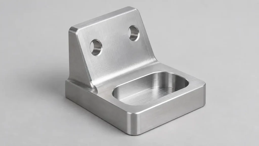
Five-axis CNC machining adds value when changing the tool’s approach direction solves a specific access, setup or tool-reach problem. Three-axis machining remains a strong option when the required features are accessible with straightforward, well-supported setups. The useful comparison is between two complete manufacturing routes—not between a basic machine and an automatically superior one.
For a buyer, the key question is: which feature becomes easier to machine or control when the tool can approach from another direction? Identify that feature before specifying five-axis machining across the whole part.
What changes when two rotary axes are available?
A conventional three-axis milling operation uses linear movement in X, Y and Z while maintaining a fixed tool-axis direction relative to the clamped workpiece. It can machine contours and curved surfaces; “three-axis” does not mean “flat parts only.” Reaching another face may require another workpiece orientation or appropriate special tooling.
A five-axis machine adds two rotary degrees of freedom. Depending on the machine configuration, the table, spindle head or both provide that orientation change. Haas describes machines that support both indexed, five-sided operations and simultaneous contouring. These are different ways of using the available motion, not separate grades of finished-part quality. Haas five-axis overview
This comparison concerns the value of additional approach directions. For the separate choice between fixed-angle cutting and changing orientation during a cut, see the indexed versus simultaneous five-axis guide.
Start with the faces the cutter must reach
Consider a hypothetical bracket with a pocket on its top and a hole normal to an inclined face. A vertical drill cannot produce that inclined hole along its intended axis while the bracket stays in the illustrated orientation. A three-axis route can reorient the part in another fixture; a suitable five-axis arrangement can orient the tool and part relative to each other while retaining the grip.
That distinction is the first potential advantage: access to several directions without manually rebuilding the setup for each one. It is not proof that every surface becomes reachable. The gripping area remains obstructed, and adjacent walls, the holder, rotary travel and the machine enclosure still constrain movement.
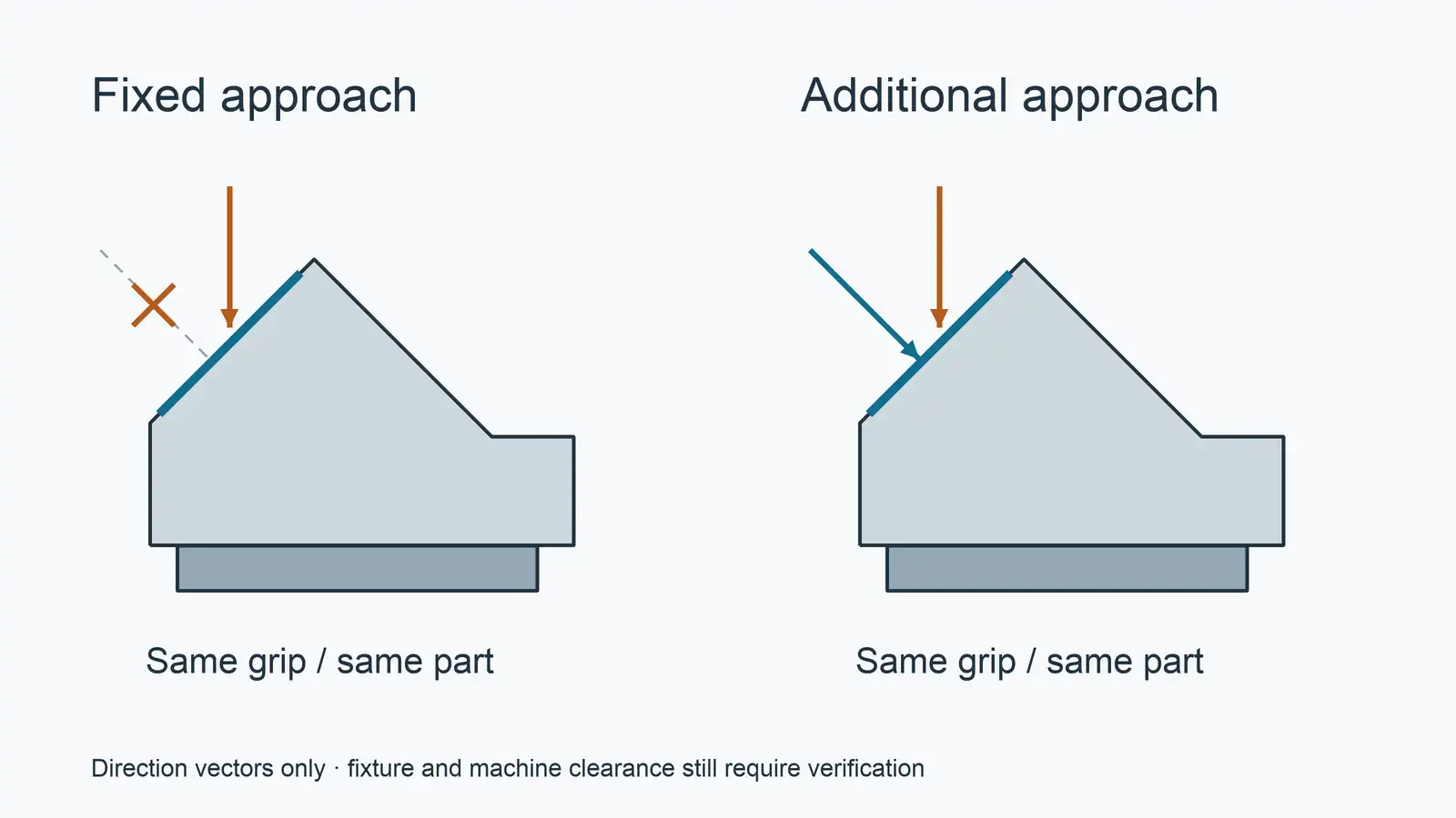
The diagram compares approach directions, not production cycle times. The part geometry and scale remain identical. No valid feeds, speeds, clearances or collision-free program can be derived from this sketch.
Autodesk’s undercut guidance provides another useful boundary: some undercuts can be machined with three-axis motion and suitable shaped cutters. Five-axis motion can expand the available access and tool choices, but “undercut” does not automatically mean “five-axis only.” Autodesk undercut machining
Fewer setups can help preserve feature relationships
Keeping several related features in one grip can remove some opportunities for error when relocating the workpiece. That is particularly worth reviewing when a bore, mounting face and hole group must relate to one another. Autodesk identifies reduced setup handling as one potential benefit of multi-axis machining. Autodesk precision machining
However, fewer setups do not eliminate fixture deflection, machine geometry errors or drawing interpretation problems. Features under the grip may still need a second operation. A part with generous relationships between faces may gain little from avoiding a simple, repeatable second setup.
Instead of demanding “one setup,” ask the supplier to mark the critical relationships on the drawing and show which operations establish them. Keep the acceptance plan separate: the GD&T and CMM planning guide explains why the inspection must follow the functional requirements rather than the convenience of the machining arrangement.
Tool reach and cutting direction can change the route
Extra orientation can sometimes let a shorter tool assembly reach the same working region. Shorter tools can be less susceptible to deflection, but the benefit depends on the actual clearance around the feature. Autodesk’s multi-axis controls explicitly address orientation, collision avoidance, tilt limits and safe linking moves. Autodesk multi-axis documentation
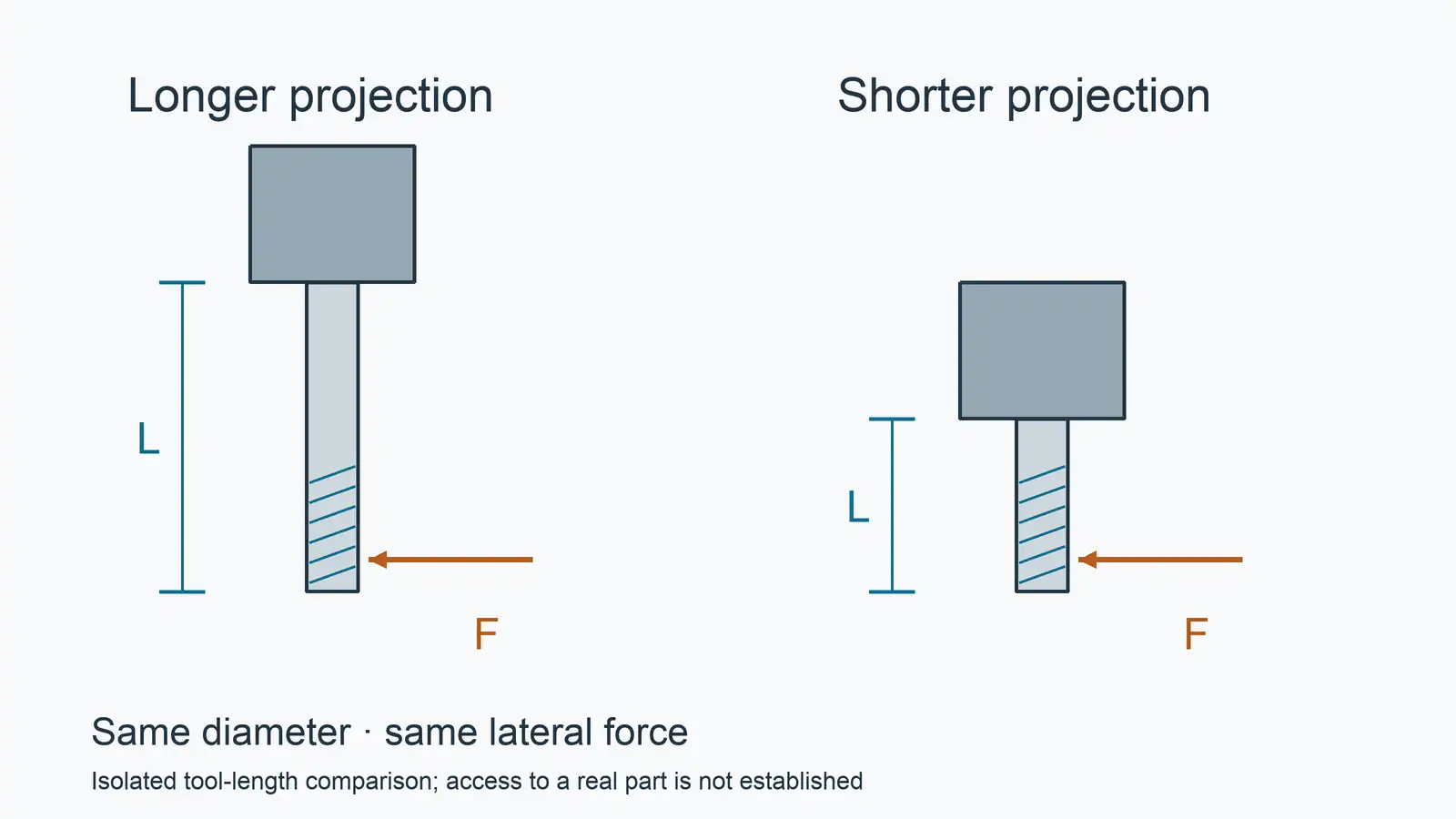
The drawing isolates unsupported tool length: the cutter diameter and applied lateral force are held constant. It does not claim that a particular part permits the shorter assembly. That feasibility question must be checked with the complete cutter, holder, stock and fixture geometry.
Orientation also changes how a tool travels across a surface. Before treating this as a finish improvement, request the proposed cutting direction and the acceptance requirement for that surface. A five-axis label is not a surface-roughness result. Machine configuration matters too: Autodesk notes that some arrangements can force longer tools because of the changing distance between spindle and rotated workpiece. Autodesk machine-configuration discussion
When is a three-axis route still sensible?
| Part situation | Starting point for the process review |
|---|---|
| Open pockets and holes from one direction | Evaluate a straightforward three-axis setup first. |
| Several accessible faces with noncritical relationships | Compare simple secondary fixtures with indexed access. |
| Angled features tied to a common reference | Ask whether keeping the grip reduces a meaningful relocation risk. |
| Restricted tool access near walls | Compare complete tool assemblies and machine clearance. |
| A changing surface orientation | Establish whether tool-axis changes solve a specific cutting constraint. |
These are review prompts, not automatic selection rules. A repeat batch with established fixtures has a different cost structure from a one-off part. Compare programming, setup, cutting, inspection and any secondary operations under the same drawing and quantity. Do not assume a higher axis count makes the total route faster or cheaper.
Ask for a feature-based proposal
Send a revision-controlled model and drawing, identify the functional surfaces, and state the quantity and acceptance requirements. Ask which features drive the suggested axis strategy, what remains for another setup, and which access or inspection issues need design input.
For five-axis machining of multi-face geometry, that feature map is more useful than a blanket request for the most elaborate machine. Ask JIZAO to review your drawing and compare the proposed route with the requirements of the actual part.






