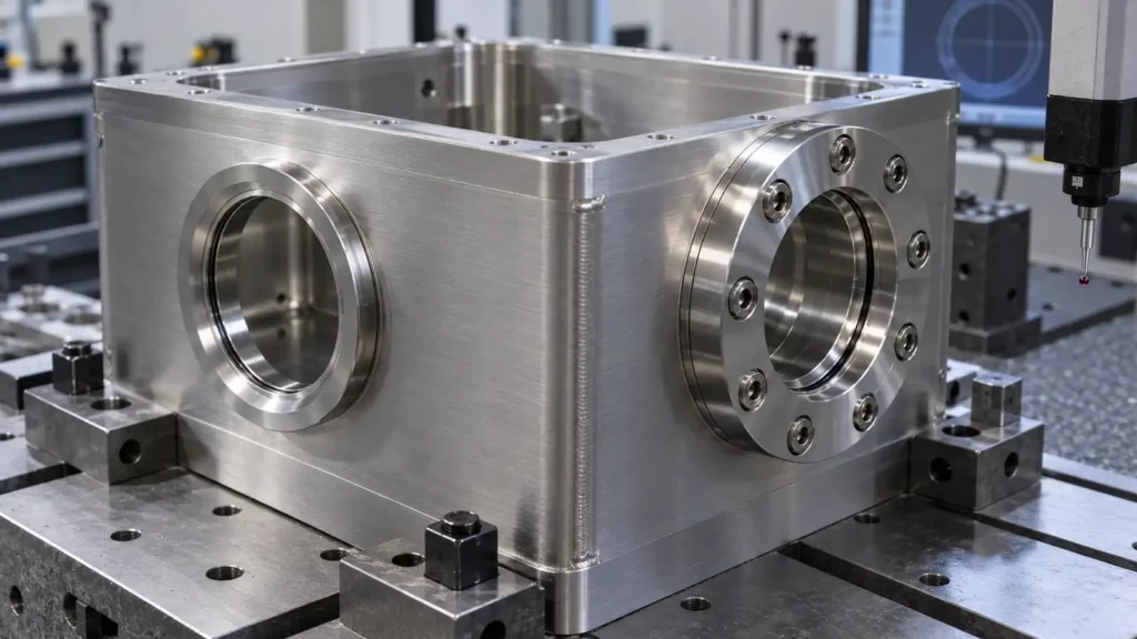
Featured image: conceptual engineering visual, not a manufactured or leak-tested JIZAO chamber.
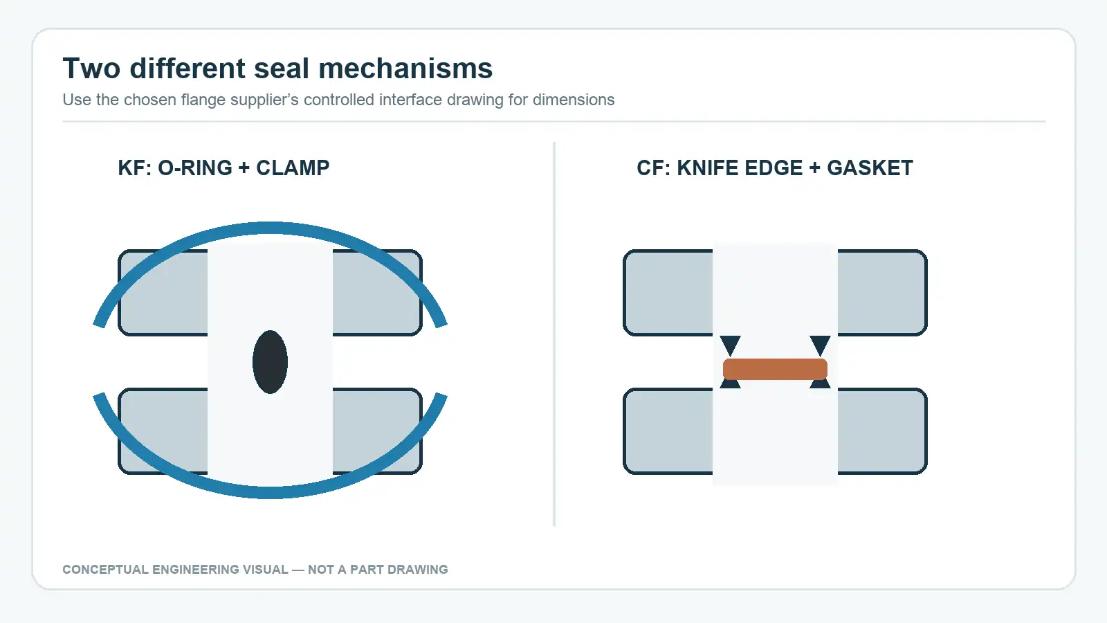
A vacuum chamber may have several ports that look similar in a CAD rendering but seal in fundamentally different ways. A KF port uses a centering ring and elastomer O-ring held between mating flanges by a clamp. A CF-style flange uses a knife edge that deforms a soft metal gasket when bolted. Treating those interfaces as generic circular holes creates avoidable drawing, machining and inspection ambiguity.
This guide is for engineers and technical buyers preparing a chamber, manifold or adapter RFQ. It is not a customer case or evidence that JIZAO fabricates leak-qualified vacuum vessels. The applicable interface drawing, material choice, cleanliness and leak acceptance must be approved for the actual system.
Select and identify the interface before detailing the port
State the flange family, nominal size and exact mating hardware or manufacturer drawing. Kurt J. Lesker's KF technical notes describe the centering ring carrying an elastomer O-ring and a clamp engaging the flanges' rear chamfers. Their CF notes describe a machined knife edge that compresses a metal gasket. A designer should not replace one sealing concept with the other just because the bore diameter looks similar. Nor should a supplier infer a flange standard from a thumbnail image.
For each port, give the mating interface drawing or controlled specification, bolt or clamp access envelope, intended gasket and assembly orientation. If the interface is purchased as a welded fitting, identify whether the CNC supplier is machining a flange blank, a welded chamber assembly, or only post-weld critical surfaces. Those are different scopes with different distortion and verification risks.
Protect the actual sealing geometry
On a KF-style port, the sealing face, alignment of mating faces, centering ring and clamp-engagement geometry work together. An ordinary O-ring groove on the chamber face is not an equivalent design. On a CF-style port, the knife edge is a functional feature; nicks, uncontrolled polishing or a protective cap contacting the edge can compromise the interface. Lesker's CF guidance emphasizes careful handling and inspection of the knife edge and a new gasket for each assembly. These are system-interface principles, not a universal dimension or leak guarantee.
The drawing should identify which face or edge is the sealing feature, its required condition, and any handling protection. Keep cosmetic deburring instructions away from the active edge unless the chosen interface specification explicitly permits them. If the port is welded into a chamber, specify whether final machining occurs after welding so any weld-induced movement is addressed in the final-state geometry. A pre-weld flange certificate alone does not establish port position or seal condition on the assembled body.
Relate multi-face ports to functional references
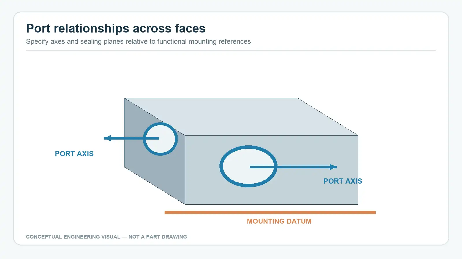
A chamber often carries a pump port, gauge port and process port on different faces. Their relationships depend on the mating equipment: axis orientation, port-center location, flange-face position and clearance to clamps, bolts or tubing may matter more than a blanket tight tolerance on every external wall. Choose functional datum surfaces that are available on the assembled chamber and can be reproduced for inspection. Keep machine fixture locators separate from released drawing datums.
For example, an external mounting plane might establish the primary reference and two accessible locating features orient the chamber; each port axis and sealing plane is then controlled relative to the mounting interface as function requires. This is an illustrative design pattern, not an instruction to use a specific ASME or ISO GD&T symbol. The drawing system and actual tolerance values must be selected by the design authority. A weldment can move as clamping is released, so say whether acceptance is in a fixture, after unclamping, or after a defined assembly step.
Plan fabrication, finishing and cleanliness as separate scopes
Ask which operation creates the chamber body, which joins the ports, and which finishes the sealing features. On a welded assembly, a post-weld finish pass can establish final interface geometry, provided sufficient material and access were reserved. On a chamber built from a machined block, the toolholder still needs clearance around adjacent bosses. Five-axis positioning may improve access to multi-face ports, but it does not replace stiffness, correct workholding or a final inspection plan. It also cannot repair a damaged CF knife edge by merely adding more axes.
Vacuum compatibility involves more than geometry. Material, cleaning, trapped volumes, elastomer choice, bakeout temperature and the complete seal stack are system-level decisions. Do not infer clean-vacuum performance from a shiny machined surface. Specify cleanliness requirements and who performs final cleaning and packaging; avoid unsupported “vacuum ready” or “leak tight” labels. Protect finished sealing surfaces through transit and assembly, and agree whether a port cap is for contamination protection or a pressure/vacuum test boundary.
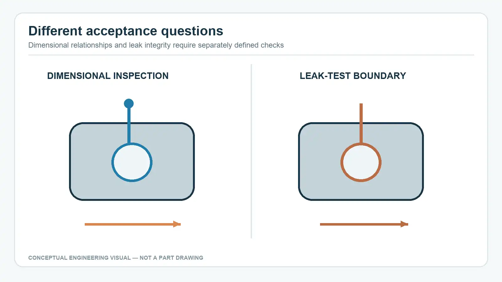
Define what inspection and leak testing will prove
Dimensional inspection can verify accessible port axes, flange-face relationships and selected interface features. It does not by itself prove a welded pressure boundary or assembled gasket joint is leak tight. Conversely, a system leak check without a dimensional report may not establish mating alignment. Define the test boundary, installed gasket/hardware, test gas and method, acceptable leak criterion, equipment sensitivity and test stage with the system engineer. Agilent's vacuum-system overview distinguishes a through-leak from outgassing or a trapped-volume effect when interpreting pump-down behavior.
Do not invent a single leak-rate target for all vacuum systems. The target depends on application, operating pressure, conductance, pumping capacity and the test method. If the specification calls for helium leak testing, document the exact boundary and acceptance procedure rather than treating “helium tested” as a self-explanatory pass condition. If testing is performed by a different party, record that responsibility in the RFQ.
An actionable RFQ includes chamber and flange drawings, mating component references, material and weld scope, quantity, datum scheme, critical port and seal characteristics, post-weld machining requirements, cleaning/handling instructions, inspection method, leak-test boundary and acceptance criteria, and required reports. State which supplied items—gaskets, clamps, bolts, caps or fixtures—are included. Ask the manufacturer to identify any uninspectable interface, inaccessible tool path or ambiguous test requirement before release.
Bottom line: decide KF versus CF at the interface level, then carry its sealing and measurement requirements through fabrication, machining and final inspection. A CNC machining review can examine port access and drawing clarity; contact the team with the controlled interface and acceptance documents for a part-specific response. No supplier performance is implied by this general guide.
FAQ
Can a KF flange and CF flange use the same sealing detail?
No. KF relies on an elastomer O-ring/centering-ring/clamp assembly; CF uses a knife edge and deformable metal gasket. Use the selected mating hardware's controlled interface drawing.
Should a welded chamber be inspected before or after welding?
The relevant final-state relationships generally need verification after any process that can move the ports. Pre-weld checks can still help process control, but cannot replace specified assembled acceptance.
Does a passed leak test prove port geometry is correct?
No. It evaluates a defined assembled test boundary under specified conditions. Geometry and mating alignment require their own acceptance checks.






