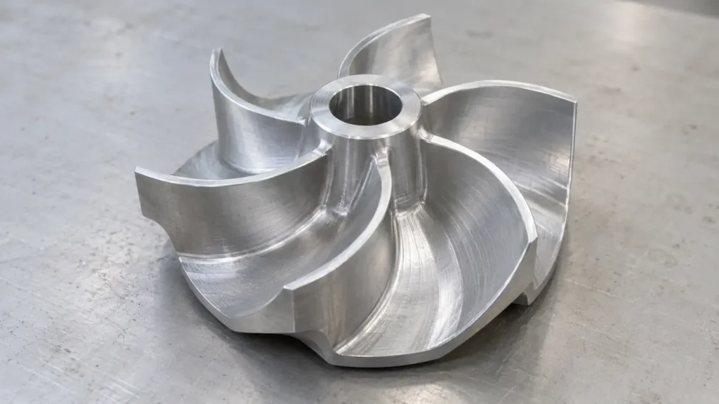
An impeller drawing is not ready for a meaningful five-axis quote merely because it includes a 3D blade model. The supplier needs to know whether the part is open or shrouded, which blade and hub surfaces are function-critical, how the central bore and mounting faces define the datum scheme, what material and stock state are required, and how the finished passages will be inspected. Five-axis tool motion can address curved blade access, but access, finishing and measurement are separate problems. This article uses a generic unshrouded impeller as a design example, not a JIZAO case or process claim.
First distinguish the geometry being requested
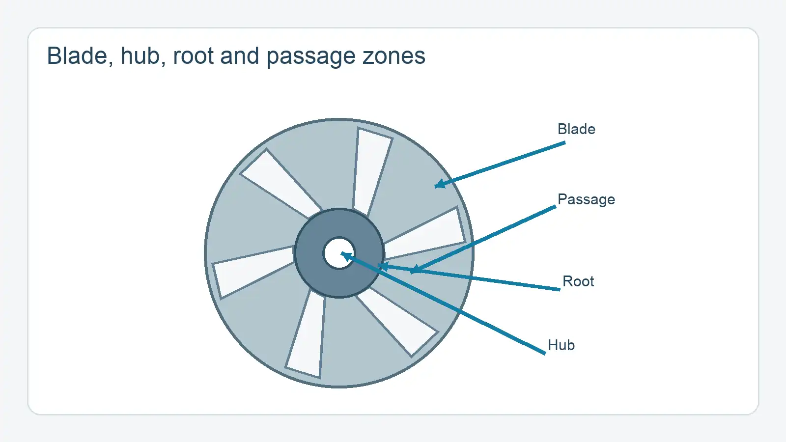
An open impeller exposes its blade passages from one side. A shrouded design closes a side with a cover or integral geometry and can create much more restricted access. Blade count, splitter blades, hub shape, blade curvature, root fillets and the smallest interblade gap change tool selection and tool-axis freedom. Autodesk's PowerMill impeller support guidance separates left and right blade, splitter, hub and shroud surfaces for CAM definition. That is useful evidence that these are distinct geometric regions, not proof that any particular impeller can be cut on any five-axis machine.
The model should be an unambiguous finished geometry, with a drawing that identifies functional characteristics. Do not make an image of a dramatic rotor substitute for section views, blade definitions or a controlled model. If the part has a separate cover, define how that cover is joined and inspected; do not quietly treat it as a one-piece shrouded blisk. When a production part has hydraulic or aerodynamic requirements, its design authority must define acceptable blade geometry and balance requirements; a generic machine shop cannot infer them from appearance.
What controls the cutter's route through a passage?
The available gap determines whether a cutter and its holder can enter, tilt and exit without collision. Blade height and curvature affect tool length and how much of the blade can be finished with side contact versus many small tool-tip passes. Siemens' NX CAM discussion of impeller access identifies reach, access and thin-blade vibration as process challenges, and describes tilting a tool to avoid adjacent walls. This is CAM application guidance; it is not a general promise of finish, cycle time or tolerance.
The hub and root fillet are especially easy to overlook. A cutter large enough for efficient blade finishing may not fit the root transition, while a small cutter held on a long tool can be less rigid. Ask whether the root radius is dictated by function or can be enlarged, and whether a residual cusp or blend zone is allowed. The process engineer can then separate roughing stock, semi-finishing and final surface strategies. The CAD model should not contain a zero-radius root that cannot be inspected or manufactured with the intended process.
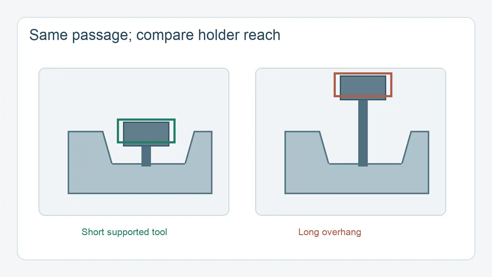
For open passages, simultaneous five-axis motion may help maintain a suitable tool direction along a curved blade. Indexed operations or a simpler route can still be useful on the bore, back face or mounting pattern. A toolpath that looks plausible on a static screenshot is not enough: verify it with the chosen stock, fixture, toolholder, machine kinematics and postprocessor. Siemens' NX turbomachinery milling training explicitly includes machine mounting and movement simulation. Toolpath verification reduces avoidable collisions but does not prove process capability or finished-part quality.
Keep locating features and blade form linked
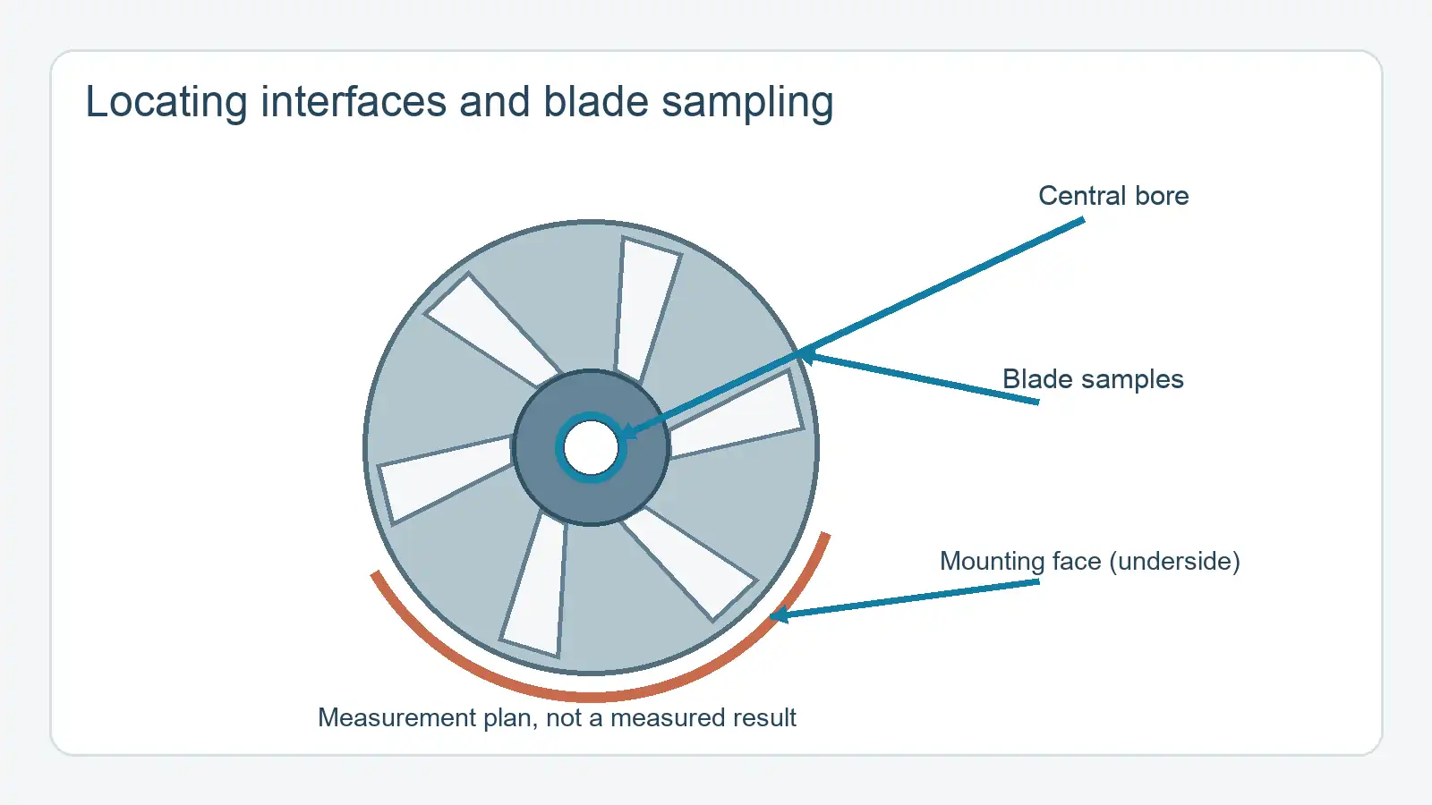
The bore, mounting face and clocking feature often govern where the impeller sits in its assembly; the actual datum scheme must follow the functional design. If blade profiles are accepted relative to that datum reference frame, machining and inspection need a coherent way to re-establish it. A temporary holding boss or sacrificial stock may make fixturing possible, but its removal can change access and demands a planned finishing/inspection sequence. Do not label a convenient chucking surface as a design datum unless it really represents the assembly interface.
State whether a profile requirement applies to the entire blade, selected sections, leading/trailing edges, the hub, or an envelope. These have very different measurement effort. Blade thickness and spacing may be assessed at defined stations, but stations alone may miss errors between them. If function depends on flow, balancing or fatigue, additional validation may be required outside dimensional inspection. Avoid implying a CMM profile scan proves hydraulic performance or surface integrity.
Decide what can really be measured
Renishaw describes a blade-measurement toolkit using programmed sweep scanning and analysis of blade surfaces. That shows a possible class of inspection method, not that any given blade can be reached or measured to an unspecified uncertainty. Probe size, approach, section spacing, datum realization, software evaluation and the part's material/temperature condition all matter. For a narrow shrouded passage, an internal surface might need another method, a design change, or an explicitly limited acceptance scope. Agree this before the order, not after finishing a first article.
A visual inspection can find damage and obvious burrs, but it cannot substitute for bore fit, blade profile or balance acceptance. Conversely, a dimensional scan does not establish a clean fluid path or operational efficiency by itself. Separate geometric inspection from assembly or functional testing; list each deliverable and responsible party in the purchase requirements.
What belongs in an impeller RFQ?
Provide the released model and drawing revision, open/shrouded classification, material specification and stock form, expected volume, central bore and mounting interfaces, blade/hub/root regions and tolerances, surface/edge condition, finish or treatment state, balance and functional-test requirements if applicable, and documentation expected at first article and repeat production. Identify any sacrificial stock or machining allowance the design permits. Ask suppliers to name inaccessible regions, proposed process split, collision review scope and inspection exceptions before a price is accepted.
Decision rule: use five-axis machining as a candidate tool for a defined geometry, not as the specification itself. An impeller becomes quotable when the blade surfaces, locating interfaces, tool access and acceptance method agree.
The five-axis machining service overview provides a starting point for a process discussion. Contact the engineering team with the released model, drawing and acceptance questions for a part-specific review; do not treat this article as a capability or quotation commitment.
FAQ
Does every impeller require simultaneous five-axis cutting?
No. Curved blades may benefit from simultaneous control, while bores, back faces and mounting features may use indexed or simpler operations. The actual part and machine determine the route.
Is a good-looking blade finish proof of aerodynamic or hydraulic performance?
No. Appearance cannot verify blade profile, balance, surface integrity or operating performance. Define separate measurement and functional tests where the design needs them.
What is the first geometry to review for machinability?
Start with minimum passage and blade-root access, then evaluate cutter/holder clearance with real stock and fixtures. The answer depends on the chosen tools, machine and acceptance requirements.






