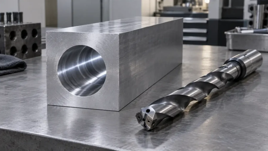
A deep hole is not just a shallow hole with more depth. Tool guidance, chip evacuation, coolant delivery, entry conditions, and access to the full bore all become more important as the path grows longer relative to diameter. A callout such as “Ø10 through” may leave the supplier unable to tell whether the requirement is a fluid passage, a precision bearing bore, or a feature whose axis must align with another face. The workable route begins with function and measurable acceptance criteria, then selects drilling and any finishing operation. No single depth-to-diameter threshold or machine type decides every job.
Define the hole's function and full geometry
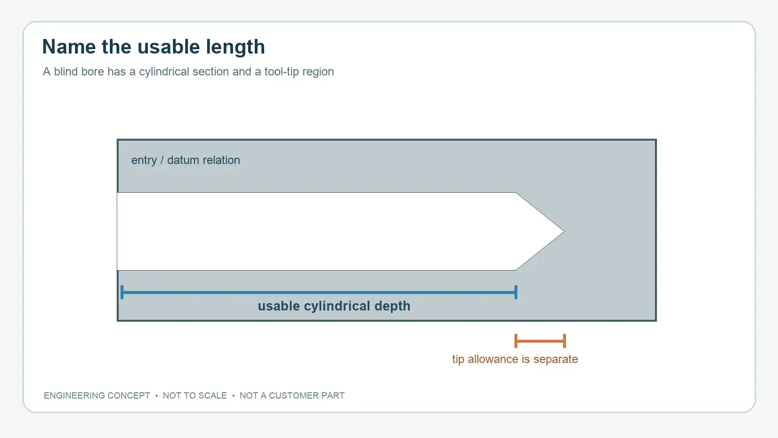
State nominal diameter, effective depth, through/blind condition, material, entrance and exit geometry, intersecting passages, and required position/orientation relative to the functional datums. For a blind hole, distinguish cylindrical usable depth from drill-point or tool-tip depth; they are not interchangeable. For a through-hole, note any exit burr restrictions or inaccessible internal junctions. If a pressurized or cleanliness-sensitive fluid path is involved, add the appropriate leak, cleanliness, or deburring acceptance criteria rather than relying on a diameter alone.
The intended use changes what must be controlled. A clearance passage may mainly require minimum open section and location. A sliding fit or seal may need size, form, surface, and axis relation over the working length. A cross-drilled manifold may need a defined intersection and a plan for removing burrs or trapped chips. The designer should identify which condition is functional and which is merely a convenient manufacturing description.
Drilling establishes access; finishing controls a different question
A conventional or modular drill can create the initial passage when the machine, tooling, material, and depth allow it. Beyond a certain reach, a guided/deep-hole system or a pilot hole may be appropriate. Kennametal's specified HTS system, for example, uses guided entry and internal coolant for a stated application range; that product limit is not a general rule for all drills, shops, or materials. Coolant delivery and chip removal must be evaluated at the actual length and material. An attractive tool catalog ratio cannot be copied into a drawing as a guaranteed capability. [1][2]
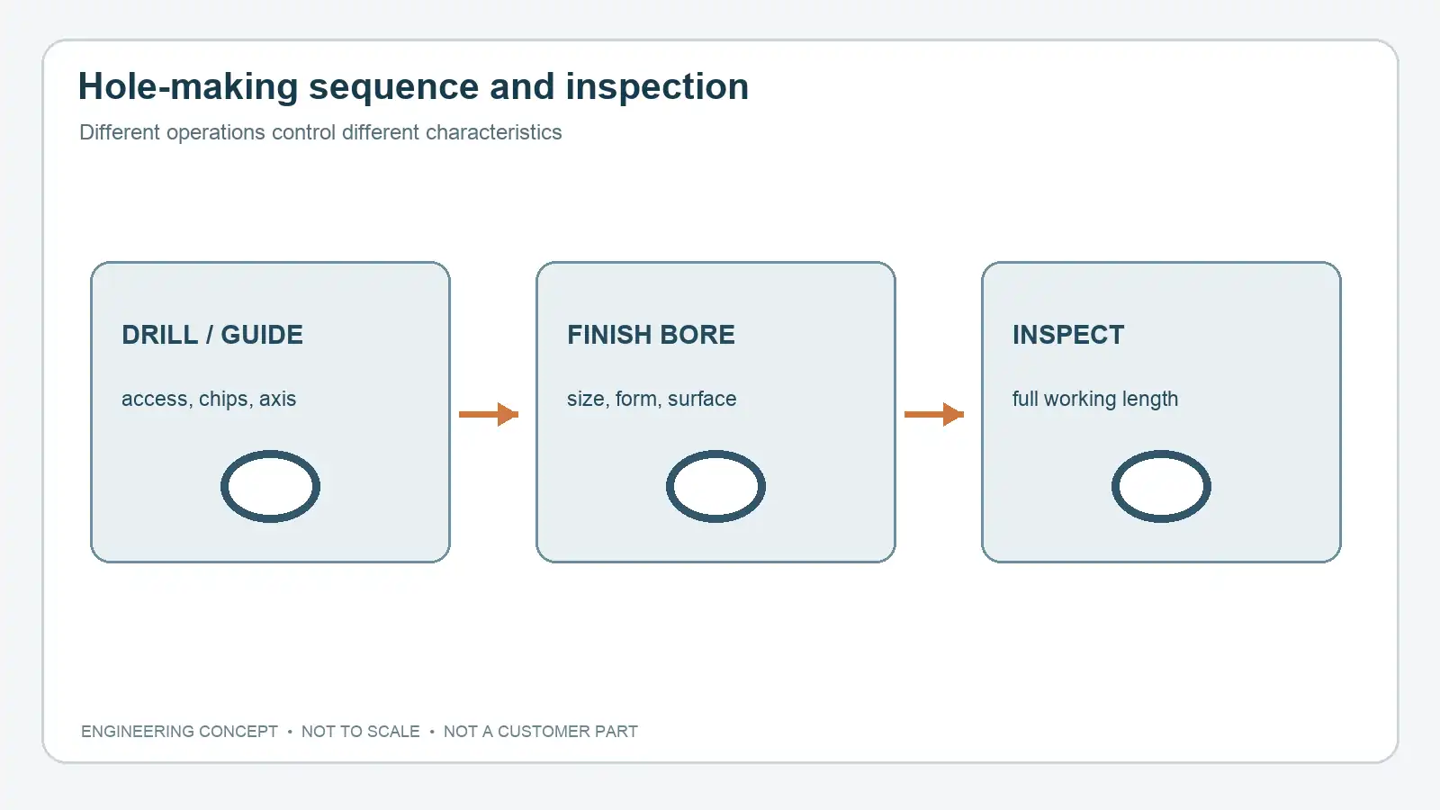
Boring and reaming are different finishing options. A boring tool can correct or establish a bore with a suitable setup and access, but tool overhang affects stability and surface/form. A reamer generally follows a prepared hole and is often used to finish size and surface; it should not be treated as a cure for a badly misplaced or wandering initial axis. Some bores require honing or another specialist finish after drilling/boring. The sequence is chosen around the demanded size, form, surface, and location, not by the word “precision.” Sandvik's boring instructions emphasize stability and chip handling, while Kennametal describes reaming as a finishing operation requiring a prepared hole. [3][5]
Plan the datums and inspection before releasing the RFQ
A diameter measured only at the entrance cannot prove the entire working length is within size. Likewise, a plug gauge may answer an assembly-go/no-go question without documenting straightness, axis position, or local taper. If the full-length condition matters, agree on a measurement method that can reach it, along with the sampling and reporting plan. Options may include suitable long-reach bore gauges, air gauging, calibrated probes, optical or sectioned validation on development parts, or specialist methods. Which option is valid depends on hole size, access, tolerance, and whether the part may be destructively evaluated. Do not put an unmeasurable tight tolerance on a hidden bore without an agreed verification route.
Define the datum reference frame from the part's assembly function. A drilled hole's tool setup or fixturing surface is not automatically the drawing datum. If several faces or intersecting bores must relate to each other, show which surfaces establish the final inspection coordinate system and how positional or orientation requirements are evaluated. Do not mix ASME and ISO notation in one drawing by assumption; choose and identify the governing drawing system. ISO 1101:2017 is an example of an ISO GPS geometrical-tolerancing standard, but its title alone does not define your feature's tolerance or an inspection plan. [4]
Risk questions to answer with the supplier
Before choosing a quote, ask:
- Can the tool enter squarely and is there room for a guide or pilot if needed?
- How will coolant reach the cutting edge and how will chips leave the full depth in this material?
- What is the proposed drill/finish sequence, and which operation controls axis location versus size and surface?
- If the hole is blind or intersects another feature, how are usable depth, burrs, and trapped chips verified?
- Which full-length characteristics can be measured nondestructively, and what development or first-article checks are needed?
These questions are more useful than demanding one machine type. Five-axis positioning may improve access or reduce some repositioning for a multi-face part, but it does not eliminate tool deflection, chip evacuation, or inspection limits inside a deep bore.
A hypothetical drawing review
Consider a long aluminum block with a blind fluid passage and a cross-port near its far end. The original drawing calls out entrance diameter and a total depth but says nothing about cylindrical usable depth, the cross-port intersection, or internal burr acceptance. The first review should add the passage's functional open length, location relative to assembly datums, an accessible cleaning/verification plan, and a distinction between drill-point depth and usable cylinder. Only then should the supplier choose the drilling and finishing route. This is an illustrative engineering scenario, not a disclosed customer component or JIZAO process result.
Bottom line
Specify deep holes by their working length, function, datum relationships, finish requirements, and inspection route. Let the supplier choose an appropriate drill, guided system, boring, reaming, or specialist finish against those measurable needs. A quoted depth-to-diameter ratio alone does not prove the finished feature will work.
Sources
[1] Kennametal, HTS Deep Hole Drilling Systems — product-specific guided/pilot and coolant information; not a universal design limit.
[2] Kennametal, KenTip FS Modular Drill System — tool guidance and coolant/chip considerations.
[3] Sandvik Coromant, CoroBore Handling Instructions — boring setup stability and chip-jamming cautions.
[4] ISO, ISO 1101:2017 public standard record — scope/status of geometrical tolerancing standard; no restricted standard content reproduced.
[5] Kennametal, Machining Guide: Reaming Tool Basics — finishing role and pre-drilled hole requirement; supplier guidance, not a universal allowance.






