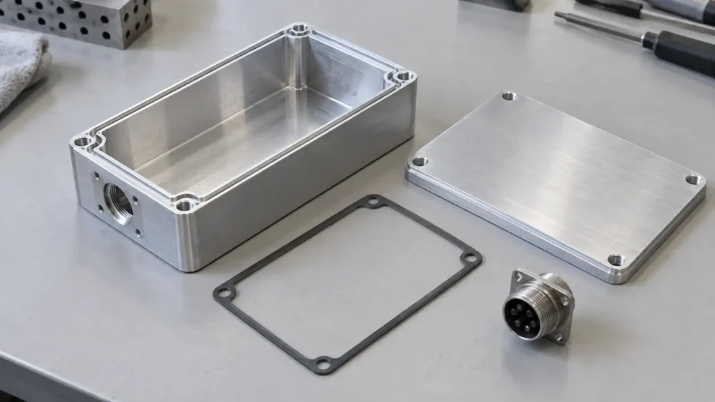
A milled metal enclosure does not become an effective EMI shield merely because its walls are conductive. The cover joint, gasket land, fasteners, surface finish and connector penetrations must form the intended electrical and mechanical interface. CNC machining can make controlled lands, grooves and panel openings, but shielding performance belongs to the assembled electronic system and its test plan. Define the selected gasket and connector hardware before freezing the enclosure drawing.
Map the enclosure's actual contact path
Mark where the cover touches the base, where an EMI gasket is compressed, where the connector shell bonds to the panel, and where protective coating or anodizing is allowed. These are not interchangeable zones. A conductive land interrupted by an insulating finish, a gap at a corner or insufficient closure force can undermine the intended contact. Conversely, leaving every surface bare may create environmental or corrosion concerns. Parker Chomerics' conductive-elastomer handbook treats flange flatness, surface condition, gasket compression and corrosion together; its product-specific advice should be checked against the actual selected gasket.
The opening size, seam length and electronics configuration may change the system requirement. Therefore, avoid claiming a dB shielding level from a CAD image or a machined land alone. The electrical/EMC owner should identify the relevant system acceptance test and which joint is being controlled.
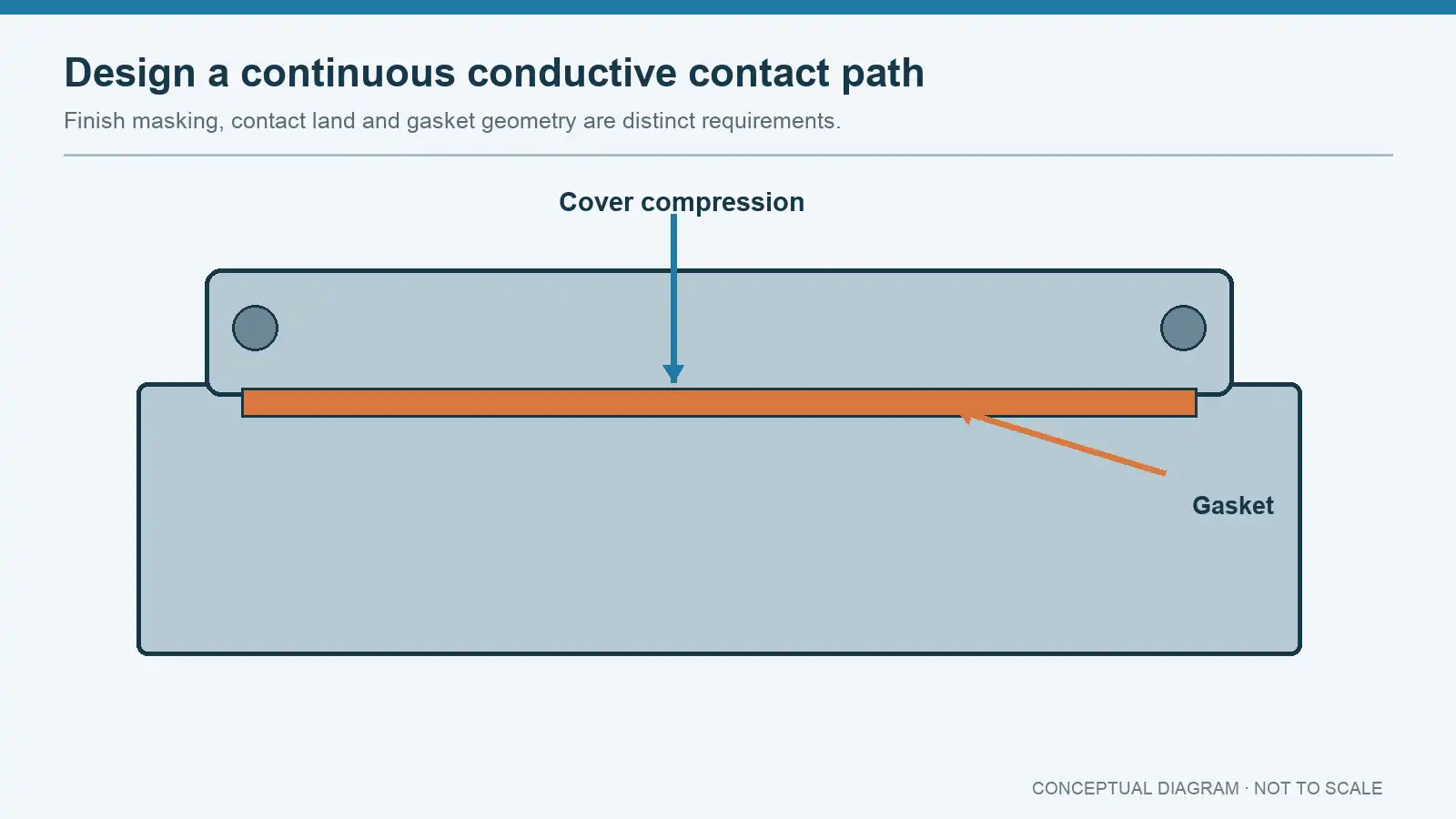
Design the gasket land as a mechanical interface
A land or groove must accommodate the chosen gasket's cross-section, compression range, tolerances and mounting method. Its continuity around corners matters, as do fastener spacing and cover stiffness: the cover can bow between screws so that nominally flat CAD surfaces do not deliver uniform contact. A compression stop may be needed for a particular gasket design; do not add one from a generic drawing without the supplier's section data. Parker's metal EMI gasket product information distinguishes open-area mounting from groove retention and discusses mating material and galvanic compatibility.
For CNC DFM, specify the land's relevant width, flatness/profile or local form, groove geometry, edge break and datum relationship to the screw pattern. Avoid a sharp burr where the gasket can tear or fail to seat. State which surfaces are to remain conductive after finishing and which may receive nonconductive coating. Where corrosion and sealing matter, select a compatible gasket/finish system with the gasket supplier rather than assuming bare aluminum is the safest answer.
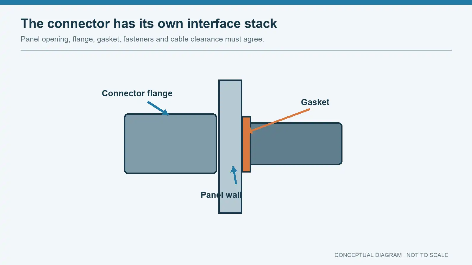
Treat the connector cutout as its own stack
The panel opening, connector flange, shell, mounting holes, gasket and cable-side clearance must be compared as an assembly. A connector that fits through the cutout may still have a flange that cannot seat, a fastener pattern that shifts the conductive contact area or a gasket that is overcompressed. Use the specific connector and gasket manufacturer's controlled drawing. Parker's D-connector gasket data shows multiple cutout configurations for connector sizes; those catalogue dimensions are examples, not a universal panel standard.
Dimension the cutout and bolt pattern from assembly datums that also locate the PCB or mating cable interface. Confirm connector orientation, keep-out and tool access for the fasteners. If the panel is anodized or painted, specify the permitted finish and masking around the flange contact with the electrical engineer and finishing partner. JIZAO's role in a CNC quote is to manufacture and verify the drawing-defined metal geometry; gasket selection, electrical bonding criteria and system EMC validation need an explicit owner.
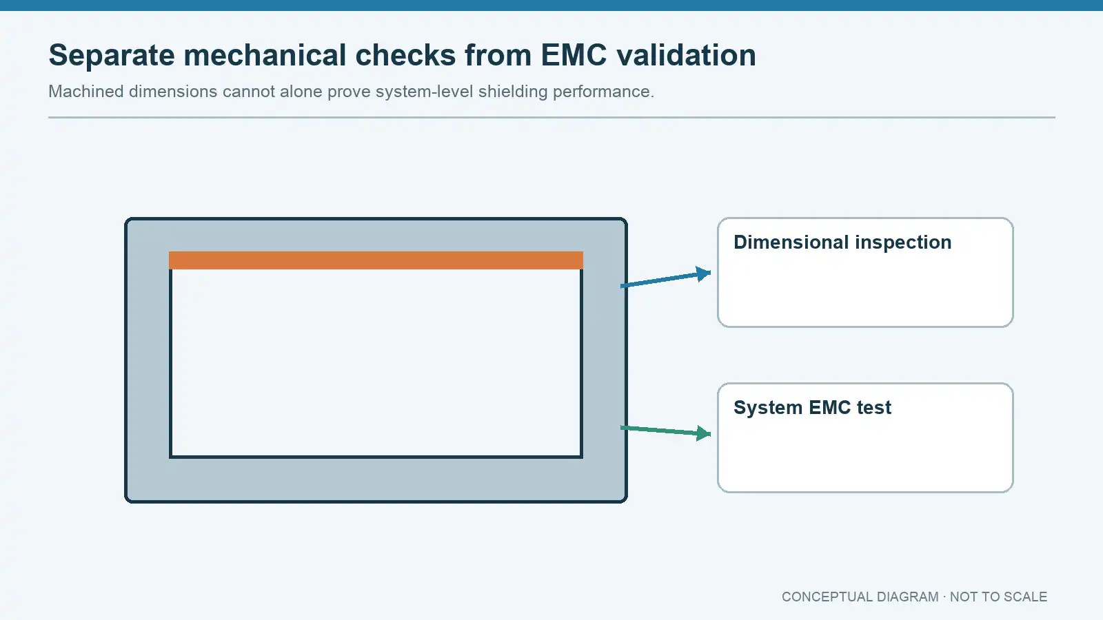
Separate mechanical inspection from electrical validation
A machining inspection can verify a land's geometry, groove dimensions, hole positions, cutout, burr condition and specified finished-state contact areas. It cannot by itself certify enclosure shielding effectiveness. Electrical continuity checks can reveal some bonding problems, but their method and acceptance limits must be defined by the system engineer; they do not replace a full EMC test where one is required. The test article must represent the assembled cover, gasket, connector, finish and fasteners, not a bare machined box.
The inspection plan should identify whether measurements are made before or after coating, whether the cover is fastened for form checks, and which surfaces are treated as product datums. A visual photo of a shiny land is not proof of conductivity or contact pressure.
For a useful RFQ, send the revision-controlled enclosure and cover models/drawings, gasket datasheet and section, connector and PCB interface drawings, finish/masking map, fastener/torque requirements where defined, target production stage and required mechanical inspection evidence. Ask the CNC supplier to flag any land, groove or cutout that creates cutter-access or inspection risk; ask the gasket and EMC owners to approve changes to the contact scheme. This division of responsibility prevents a precise enclosure from being mistaken for a validated shield.






