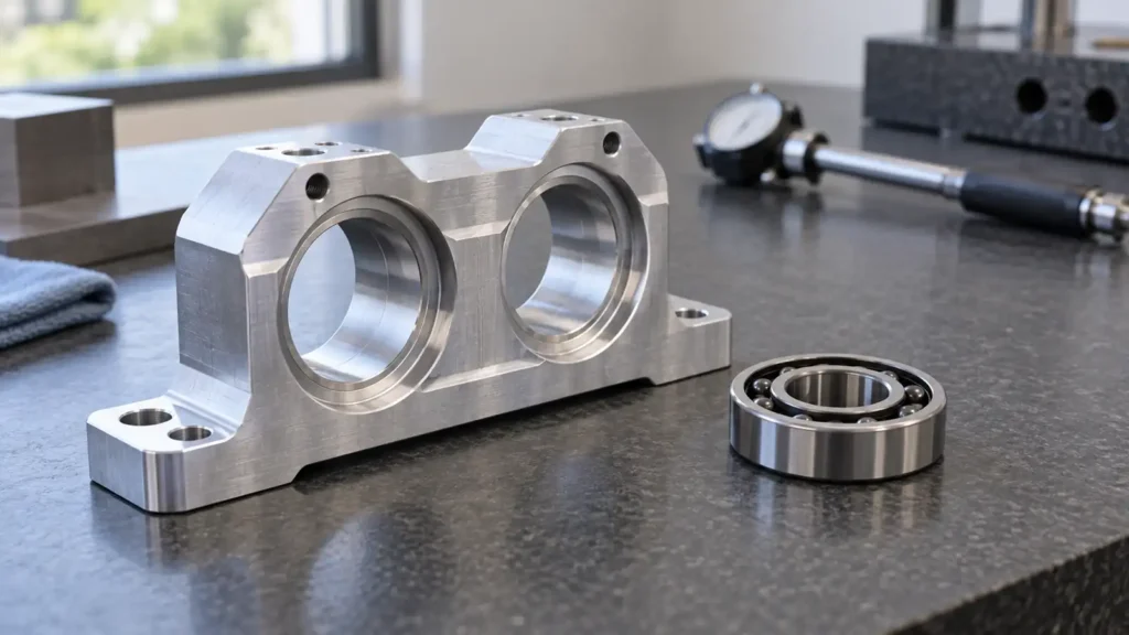
A bearing housing bore should not be specified from a generic “tight CNC tolerance.” Its diameter, form, shoulder geometry and relationship to the second bearing or mounting datums must support the chosen bearing, load, thermal behavior and locating/non-locating arrangement. A bore that measures the right size at one point can still distort an outer ring, tilt its axis or stop intended axial movement. Start with the bearing manufacturer's guidance, then define what the finished housing must demonstrate.
Decide what the bearing arrangement must do
Identify the exact bearing designation and whether the housing ring is intended to be fixed or allowed to move axially. Note load magnitude and direction, speed, shaft/housing materials, assembly method and operating temperature range. SKF's rolling-bearing catalogue explains that fit selection changes with rotating or stationary load, mounting needs, shaft and housing design, and temperature. Its recommendations are bearing- and arrangement-specific, not a single H-class to copy into every CNC drawing.
A tighter housing fit may resist ring movement under some loads, but it can change bearing internal clearance or interfere with the axial float required at a non-locating position. A thin-walled aluminum housing and a robust cast-iron housing also respond differently to interference and heat. Ask the bearing/application engineer to choose the arrangement and allowable fit; the machine shop should not infer it from the model alone.
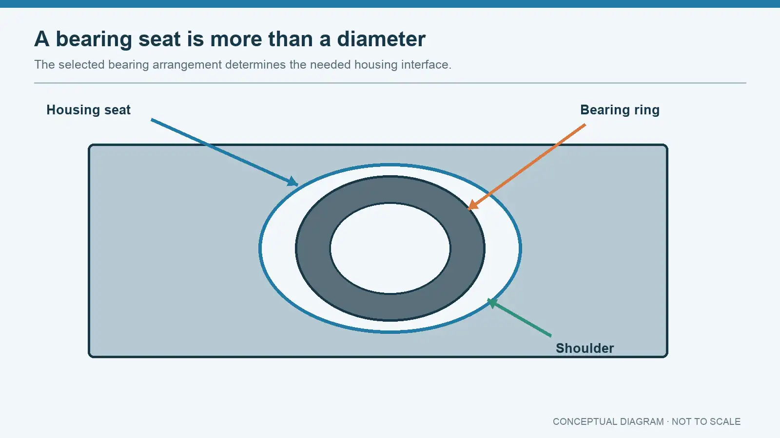
Specify more than bore diameter
The seat needs enough geometric integrity to support the ring. Control the necessary bore size and form, seating length, shoulder face/abutment, lead-in edge and relationship to the functional datum system. A rough-looking bore and a form error are not the same problem: a size reading alone will not expose lobing or taper, and a low roughness value does not prove roundness. Schaeffler's mounting handbook discusses form and position of shaft and housing seats and notes that second-seat alignment depends on the bearing's allowable angular adjustment.
For two bearing seats, define the relationship that makes the shaft work. Are both bores intended to share an axis? Is a mounting face the primary product reference? Which shoulder locates the ring axially? The drawing should use one declared GD&T system and specify the functional datum features. Do not substitute an arbitrary “coaxial within X” note without deciding how the requirement will be interpreted and measured. A removable cap or split housing may require an assembled-state drawing and matched-part controls; inspect it in the condition in which the bearing seats are formed and used.
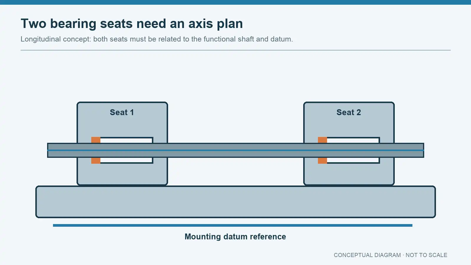
Plan machining around the critical relationship
A common-bore operation in a suitable fixture may reduce setup transfer between seats, but bore geometry can still shift from cutting force, material movement, clamping or temperature. If the housing must be reoriented, establish how the functional references are recovered. The machine's positioning specification is not finished-part process capability. Roughing, stabilization when appropriate, finishing and unclamped inspection should be considered in the context of the actual wall thickness and stock condition; the sequence is part-specific, not a universal recipe.
If the part is anodized, coated or otherwise finished, state whether the seat is masked, finished to size afterward or accepted in the final treated condition. A finish that changes the effective bore or shoulder contact must be addressed in the drawing and process plan. Do not leave the bearing seat's acceptance state implicit.
Inspect size, form and axis relationships separately
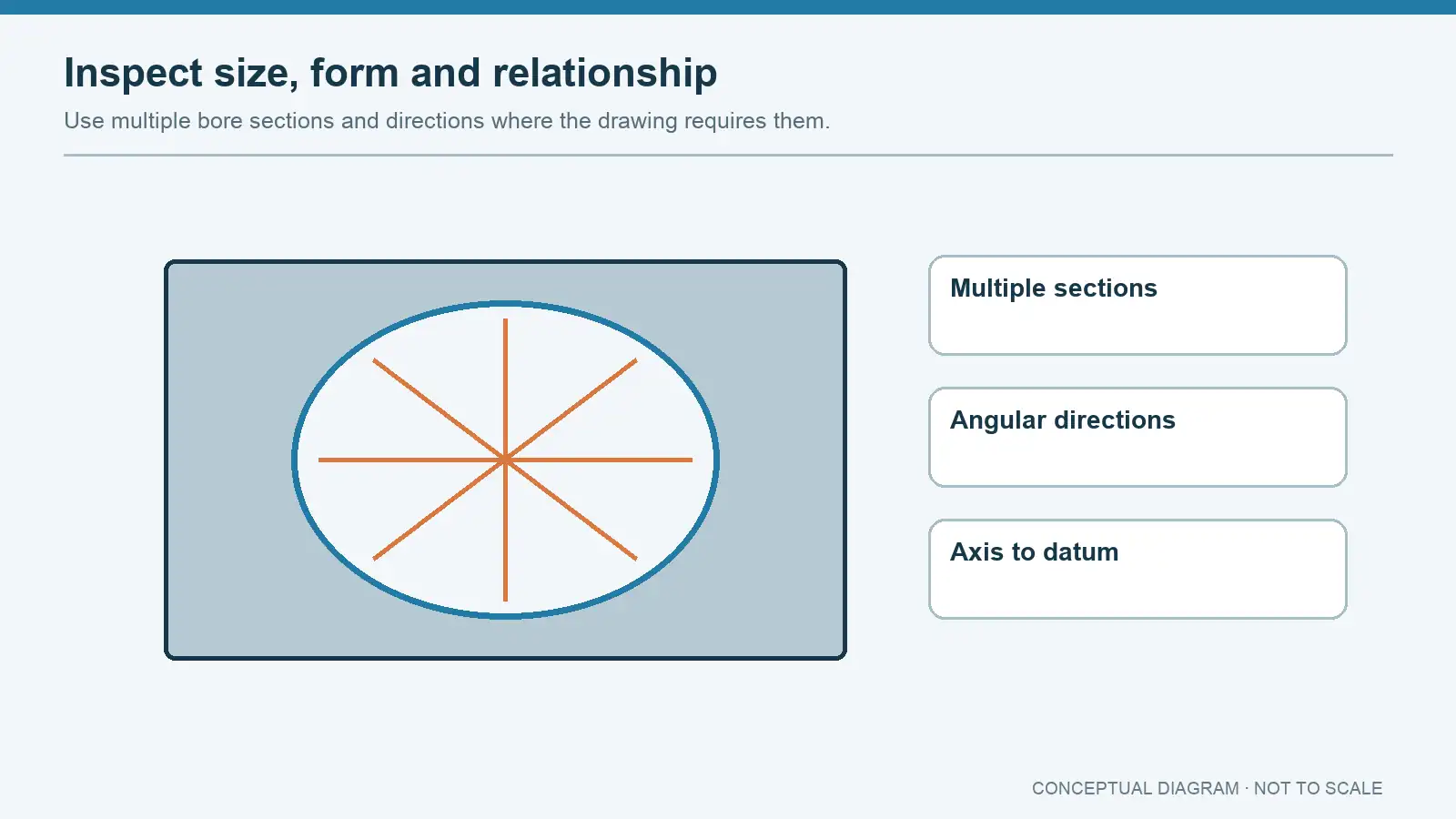
Measure bore diameter at more than one axial location and angular direction where the specification calls for it. SKF's bearing-seat measurement instructions recommend checks at multiple places and directions to expose dimensional and form variation. A calibrated bore gauge or inside micrometer can support diameter checks; it does not, by itself, prove the relationship between two bore axes and a mounting datum. A CMM or suitable dedicated gauge can evaluate that relationship only with correct datum realization, probe access and measurement uncertainty. The inspection method should be agreed to the drawing characteristic, not selected by instrument prestige.
The RFQ package should include the bearing manufacturer's exact designation, shaft and housing materials, load/rotation arrangement, expected thermal state, 3D model and drawing, controlled bore/shoulder features, final surface-treatment condition, assembly state and required measurement record. Ask the supplier to identify the proposed boring/finishing setup, datum transfer and inspection plan. If the bearing selection or functional fit is still open, resolve that with the bearing/application engineer before a CNC supplier commits to a bore tolerance.






