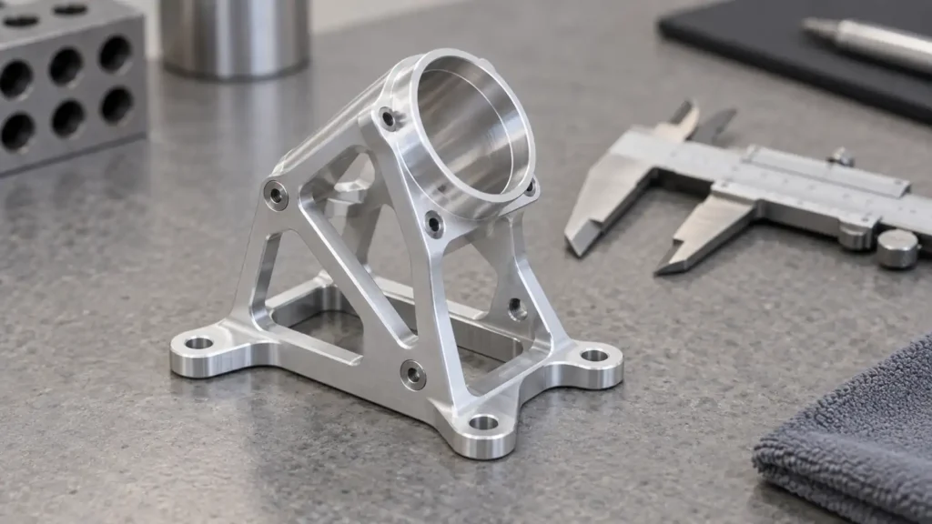
A small civilian drone does not make every part a five-axis part. A flat mounting plate may be cut and drilled with a simpler route; a turned spacer belongs on a lathe. Five-axis capability becomes relevant when a compact machined component combines important features on several faces, inclined interfaces or difficult tool access—and when the selected route preserves the relationships that matter after machining and inspection. The question is about geometry, setup transfer and verification, not the size or marketing category of the drone.
Start with the component, not the airframe
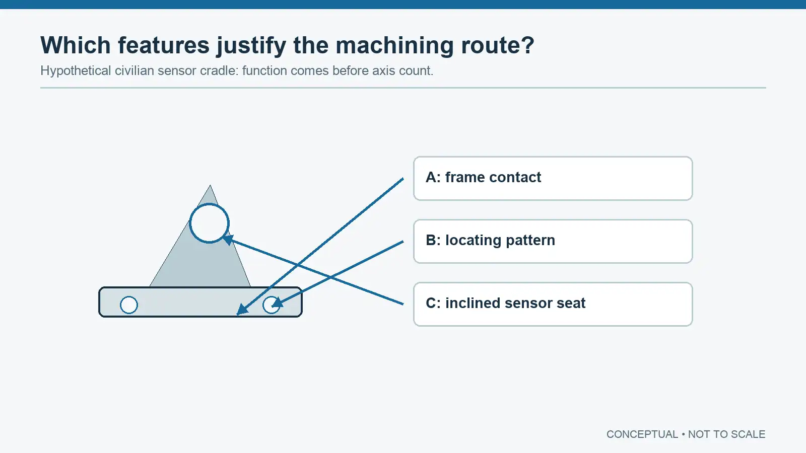
Consider a hypothetical civilian sensor cradle that locates a small camera module to a frame. It could contain a base mounting face, an inclined sensor bore, side-access fastener holes and pockets intended to reduce mass. This is a design example, not a JIZAO customer part or reported manufacturing result. Its critical characteristics might be the sensor bore's orientation and position relative to the base and a locating hole pattern. Its outer contour may be less critical if it only provides clearance.
Before selecting machinery, define which interfaces carry load, position a sensor, manage heat or establish clearance. State material, minimum functional wall sections, finish and the accepted final mass range if mass is a real system constraint. Avoid removing material solely because a pocket looks sophisticated: an extra pocket can increase chatter, inspection work and fragility without helping the product. Thin-wall milling requires staged stock removal and appropriate support because cutting forces can deflect a wall; Autodesk's thin-wall guidance explains the deflection mechanism.
Three-axis, indexed 3+2 and simultaneous five-axis solve different problems
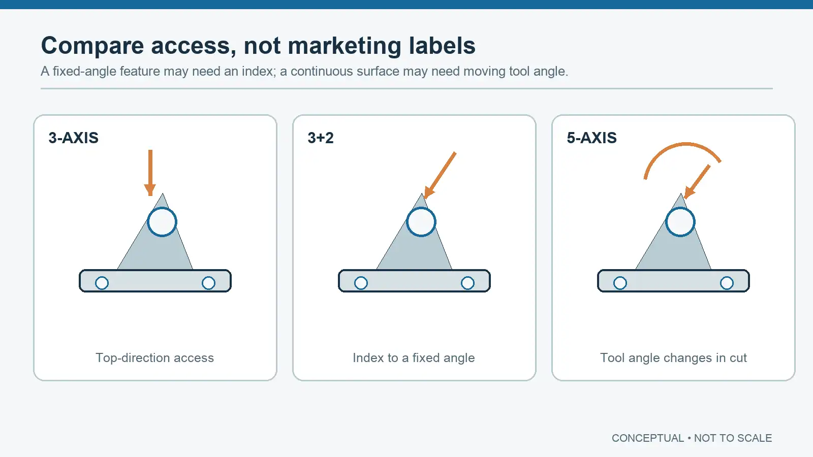
Three-axis milling can be appropriate when most critical surfaces can be reached from one tool direction, or when additional setups have robust reference features. Indexed 3+2 rotates the tool or part to a new fixed orientation and cuts there. It can help with an inclined bore, angled face or multiple sides when tool access and holder clearance allow it. Simultaneous five-axis moves rotational and linear axes during the cut; it may be necessary for a continuous surface, an undercut or a tool-axis-control requirement that fixed orientations cannot satisfy. Autodesk distinguishes indexed 3+2 from simultaneous motion in its five-axis overview and discusses access and clearance in its 3+2 guidance.
For the hypothetical cradle, an inclined planar mounting face and straight bore might be manageable with indexed 3+2 rather than continuous five-axis motion. If the only other detail is a flat base and simple holes, two well-controlled three-axis setups may also compete. The answer depends on feature access, fixtures, required bore-to-base relationship, batch size and inspection—not the word “micro-drone.”
| Feature or constraint | First route to evaluate | What could change the decision? |
|---|---|---|
| Flat plate, tabs and through-holes | Sheet process or three-axis CNC, depending on material and section | Bends, critical machined seats or a required monolithic form |
| Rotational spacer or bushing | Turning | Cross-features or non-rotational interfaces |
| Compact bracket with several fixed-angle machined faces | Three-axis setups or indexed 3+2 | Datum-transfer risk, access, holder collision and fixture stability |
| Continuous sculpted surface with controlled tool angle | Simultaneous five-axis candidate | Surface function, viable toolpath and measurable acceptance |
These are candidates, not guaranteed cheapest routes. A five-axis machine can still require secondary setups or specialized tooling. More degrees of freedom also introduce machine and process errors; NIST's five-axis geometric-error research is a reminder not to equate axis count with finished-part accuracy.
Protect datum relationships through a multi-face route
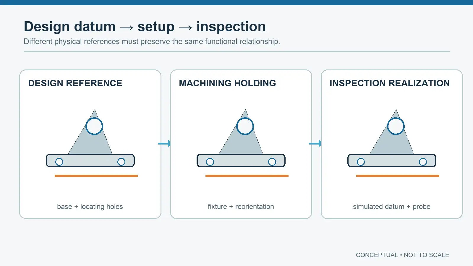
The product's datum scheme should represent how the component locates in the assembly. A machining fixture is a manufacturing reference; a CMM or gauge has its own physical realization of the drawing datum features. They should be connected by a process and inspection plan, but they do not have to be identical pieces of hardware. For the cradle example, if the base face and two locating features establish the assembly reference, the inclined bore's position and orientation should be defined and checked relative to that reference—not merely measured from a convenient outside edge.
A multi-face route may cut the base and locating features first, then use qualified references for later orientations. Alternatively, indexed machining might reach several important surfaces while the part remains in one holding. That may reduce one source of transfer error, but it does not erase tool deflection, thermal effects, fixture distortion or measurement uncertainty. NIST's machine-tool calibration review covers multiple machine error sources. The correct route is the one that can demonstrate the required relationship at an acceptable cost and risk.
Lightweight geometry is a process and inspection problem
Thin ribs and deep pockets can reduce mass but reduce stiffness during cutting. Finishing one side of a wall before removing stock on the other can make the remaining material respond differently to cutting force. Autodesk's thin-wall machining guidance recommends considering alternating depth and stock strategy to avoid damage in relevant cases. There is no universal minimum wall thickness here: alloy, stock condition, geometry, tool, reach, support and finish all matter.
Define what must remain after the final surface treatment. A tight-fitting sensor seat or electrical contact may need masking or a post-finish dimension callout, while another surface may tolerate coating buildup. Do not assume the same acceptance condition for raw and finished parts. The quote should say which operations and inspections occur before and after finishing.
What to send for an RFQ—and what to ask back
Provide the revision-controlled model and drawing, the civilian application context needed for function, material and finish requirements, target quantity and revision stage. Mark critical interfaces, datum features, thin sections, inaccessible cavities and the final-state dimensions that must be inspected. If mass matters, give the permissible mass or system budget rather than an unsupported request to “make it as light as possible.” Specify the governing drawing interpretation system and avoid mixing symbol conventions from different systems on one drawing.
Ask the supplier to compare a reasonable three-axis or 3+2 route against simultaneous five-axis only where the geometry justifies it. Request the proposed setup count, how the datum relationship is transferred or preserved, any holder-access risks, thin-wall strategy, finishing assumptions and an inspection approach for the critical features. If the supplier proposes a design change, ask what function it preserves and what it compromises.
The practical answer is conditional: use five-axis when multi-face access, controlled tool orientation or reduced datum-transfer risk creates a verifiable benefit for this specific component. Use a simpler route when it makes and measures the same functional requirements more reliably. A small drone is an application context, not a machining specification.






