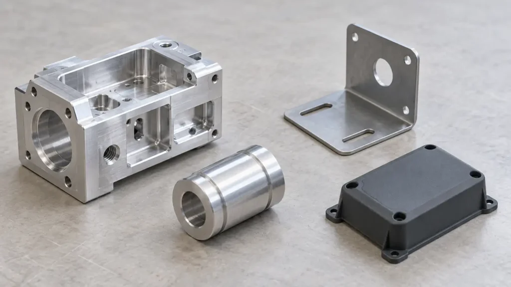
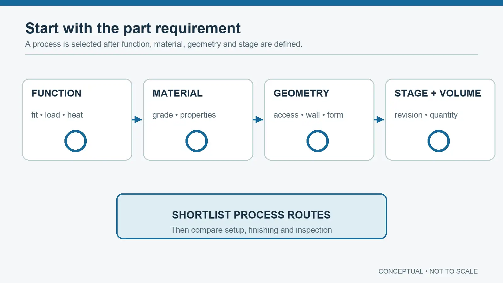
Choosing a process is not a contest between a CNC machine and a 3D printer. It is a decision about what a part must do, which material and geometry deliver that function, how many parts are needed at each product stage, and how the result will be verified. A process that is sensible for a design-validation batch may be wrong for repeat production—or it may remain the best route if the geometry changes often. Use the sequence below to narrow the options before requesting prices.
Start with the job the part performs
List the interfaces that locate, carry load, seal, conduct heat, guide motion or provide appearance. Then distinguish non-negotiable requirements from preferences. A thin cover with bends and fasteners presents a different manufacturing problem from a bearing housing with bores on several faces. The drawing should identify critical dimensions and functional datums, not merely call the entire part “precision.” An overall machine specification cannot substitute for a finished-part acceptance requirement; NIST's machine-tool calibration review explains why geometric, thermal and volumetric errors matter in practice.
Ask whether the material is mandated by performance or still open to design. An aluminum heat-spreading housing, a formed steel bracket and a polymer enclosure may serve adjacent roles but need different design rules. If the material can change, compare the product requirement first; do not force the same CAD geometry through every process and expect a fair cost comparison.
Match the geometry to a process family
The table is a screening guide, not a capability or cost guarantee. Each row has exceptions that depend on tooling, stock, feature access and supplier capability.
| Part pattern | Process worth evaluating | Main design question |
|---|---|---|
| Rotational shaft, spacer or sleeve | CNC turning, sometimes with milling for cross-features | Can the critical geometry be made and checked about a common axis? |
| Prismatic metal part with pockets, bores and mating faces | CNC milling | Can tools reach the features with stable workholding and an acceptable setup plan? |
| Mostly constant-thickness plate with bends | Sheet-metal fabrication | Are bends, flanges and hole-to-bend relationships compatible with the material and tooling? |
| Repeated near-net-shape metal geometry | Casting or die casting, often followed by machining | Are tooling, draft, material behavior and secondary machining justified by the production plan? |
| Repeated polymer cover or enclosure | Injection molding | Can the part accommodate draft, wall and tooling constraints, and is the tool investment justified? |
| Rapidly changing or inaccessible geometry | Additive manufacturing | Does the printed material and finishing route satisfy the final functional requirement? |
| Very narrow internal cut or feature unsuitable for a conventional cutter | EDM as a secondary or specialist process | Is the material electrically conductive, and what recast/surface and inspection requirements apply? |
For sheet metal, bend radius, flange length and nearby holes are process-dependent; the Protolabs sheet-metal design toolkit gives examples, but its values are not universal. An injection-molded part should be designed for the mold rather than copied unchanged from a machined prototype: Protolabs' injection-molding basics discusses draft and wall design. Additive and molding are not separated by one magic quantity: material, geometry, function and stage all affect the comparison, as Protolabs notes. NADCA's die-casting standards cover tooling and design rather than presenting casting as a no-tooling shortcut. Makino explains why an EDM route may require review of a thermally affected or recast surface layer.
Within CNC, choose access and setups—not an axis count slogan
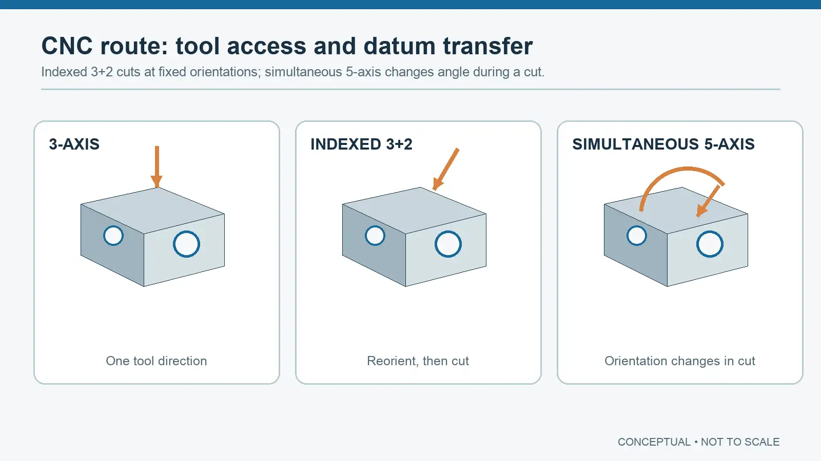
If milling is plausible, first test whether a three-axis tool can reach the critical features without excessive tool overhang or a second orientation. A second setup may be straightforward if the part has reliable transfer references and the important relationships can be inspected. Indexed 3+2 machining reorients the part or tool, then cuts at a fixed orientation. Simultaneous five-axis machining changes the orientation during cutting; it becomes relevant for certain continuous surfaces, undercuts or tool-angle-control problems. Autodesk's 3+2 guidance explicitly discusses access, holder clearance and stiffness, while its five-axis overview distinguishes indexed from simultaneous motion.
Five-axis availability does not automatically make a part cheaper or more accurate. Extra programming, fixturing, collision checks and verification can offset reduced re-clamping. Conversely, several three-axis setups can create real datum-transfer and handling risk. Compare routes against the same critical feature relationships, quantity and inspection plan. A split design or a different process family may sometimes simplify the product more than adding axes.
Compare total delivered cost across the product stage
Unit-price quotes hide different scopes. Separate one-time engineering and tooling, raw material, machine or forming time, secondary operations, finish, inspection, yield and logistics. For a prototype, speed of design change and evidence about function may dominate. For a stable repeat part, tooling and process control can become more important. There is no general quantity at which a cast, molded or printed part always becomes cheaper than a machined one; geometry, material, revisions and local supply conditions change the crossover.
Specify whether the quote is for proof-of-concept, engineering validation, pilot build or recurring supply. If a metal casting still needs critical faces and bores machined, include those operations and the final inspection. If a printed part needs machining or sealing, price the whole route. If an anodized aluminum part has post-finish fit requirements, define what is measured after finishing. A fast first piece and a stable production route are related but distinct decisions.
Use a decision path before sending the RFQ
- Function: What interfaces, loads, environment and failure modes matter? Which dimensions are critical to assembly or performance?
- Material: Is the grade fixed? Are substitutions allowed, and what properties must remain?
- Geometry: Is the part rotational, constant-thickness, prismatic, moldable, castable or only feasible through a hybrid route? Identify tool or mold access.
- Stage and quantity: State current batch size, expected revision rate and a credible future volume range, without treating that forecast as a purchase commitment.
- Quality and finish: State governing drawing system, critical datums, post-finish acceptance, inspection records and any traceability requirement.
- Route comparison: Ask each supplier to identify assumptions, secondary processes, tooling charges, change costs and the features that drive lead time or risk.
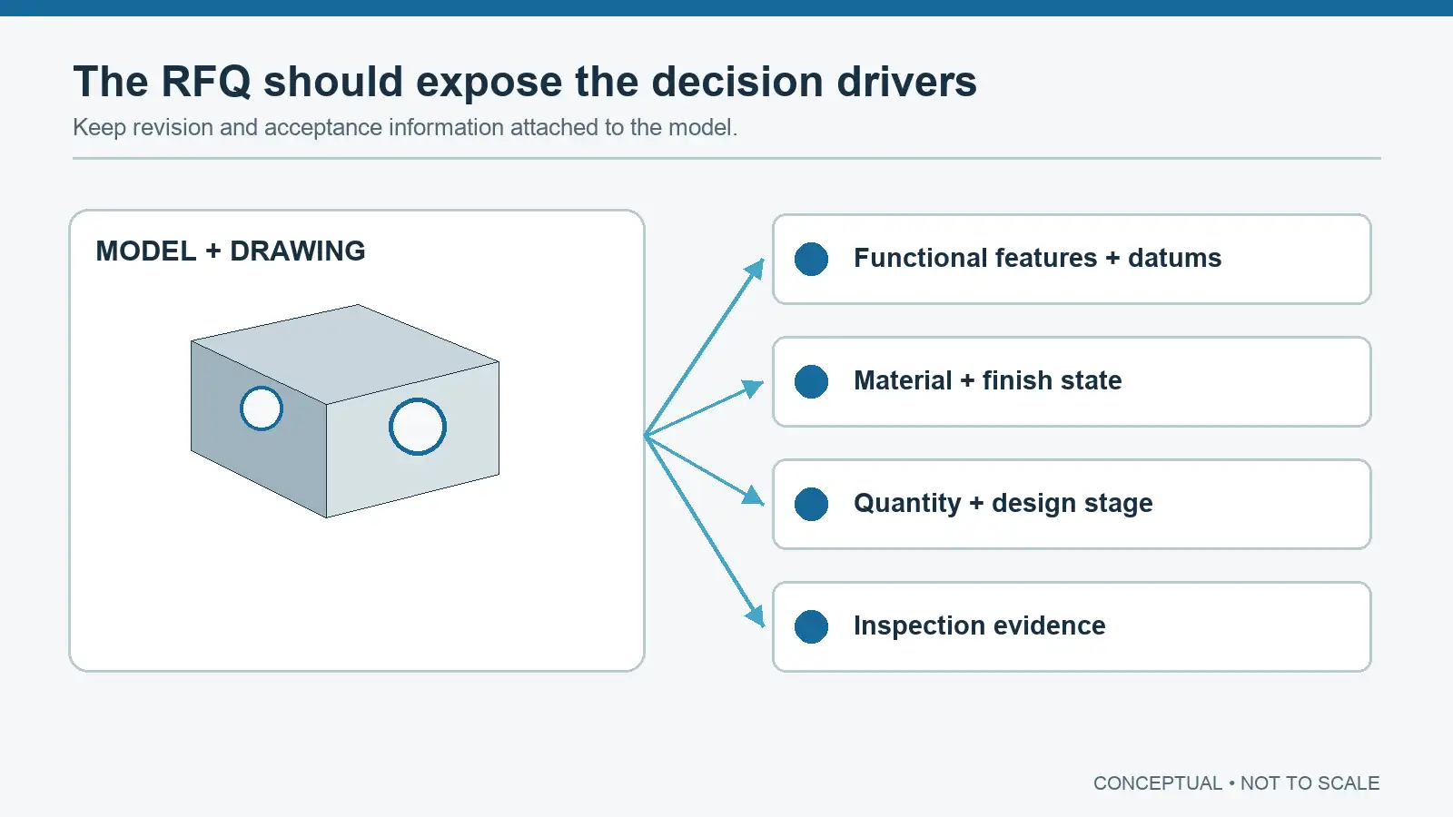
Send a revision-controlled 3D model and drawing (or an unambiguous model-based definition), material and finish specifications, quantity by stage, mating-interface context, critical-to-function features and required inspection evidence. Ask for at least one alternative route when the design is not frozen. A useful DFM response explains which feature drives a proposed process change and what that change does to function, cost and verification. That is more actionable than asking “CNC or 3D printing?” without a defined acceptance target.
A practical rule for the first decision
Select the simplest process route that can make and verify the functional features at the required stage and quantity. Revisit the choice when the design stabilizes, volume changes or inspection exposes a weak assumption. CNC machining is often useful for configurable metal parts and controlled interfaces; it is not the universal answer to every enclosure, bracket or high-volume shape. The right selection remains an engineering and sourcing comparison, not a promise tied to a machine label.






