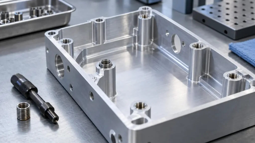
Threaded inserts can give an aluminum component a reusable steel thread, support repair, or move wear from the parent material to a replaceable element. They also add a second engineered interface: the insert must be retained in the aluminum while the fastener functions inside it.
The correct drawing therefore needs more than a final thread size. It should identify the insert system, length, parent-hole preparation, installation condition, finish sequence and acceptance evidence.
Quick answer
Select the insert family from functional needs—load, repeated assembly, locking, serviceability, temperature, corrosion and available wall thickness. Use the insert manufacturer's current hole, tap, countersink and installation instructions. Specify whether the supplier installs the insert, when surface finishing occurs, what hardware revision applies, and how installation is verified.
Choose the insert family by function
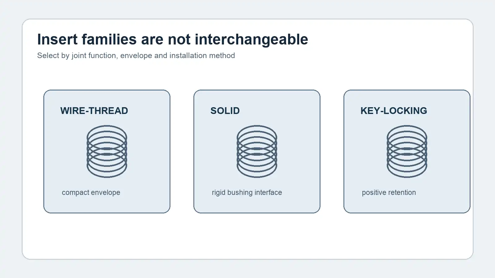
Common metal insert categories include wire-thread inserts, solid threaded bushings and mechanically locked or keyed inserts. These names describe families, not interchangeable parts.
- Wire-thread inserts are compact and can provide a durable internal thread with relatively small external envelope.
- Solid inserts can provide a rigid bushing-style interface and may offer sealing, locking or repair variants.
- Key-locking or mechanically retained inserts add positive locking features but usually need more radial material and installation access.
Do not convert one catalog's preparation dimensions to another product by nominal thread alone. External thread form, tap, countersink, set-down, tang or drive features and installation tooling can differ. Specify an approved manufacturer part number or a controlled performance specification with permitted equivalents.
Start from the joint, not from the catalog hole
The insert length and parent-material engagement must support the joint loads without stripping the aluminum, pulling out the insert or failing the fastener. Manufacturer design data commonly relates insert length to parent-material shear strength and bolt strength, but the resulting choice still depends on load type, preload, edge distance, boss geometry and service condition.
Ask these questions before selecting the insert:
- Is the joint repeatedly assembled or installed once?
- Is prevailing torque or another locking method required?
- Can the insert be replaced without damaging the component?
- Is the load primarily tensile, shear, cyclic or impact?
- Does the assembly see elevated temperature, vibration, moisture or conductive fluids?
- Is galvanic corrosion between the insert, fastener and aluminum controlled?
Avoid a universal statement such as “a 1.5D insert is enough.” Catalog lengths are often expressed as multiples of nominal thread diameter, but the correct length is application-specific.
Parent-hole geometry controls installation
The insert supplier normally defines the drilled diameter, special tap, tapped depth, countersink or chamfer, minimum material thickness and tool clearance. For a blind hole, distinguish:
- usable installed thread length;
- insert set-down below the surface;
- tap lead and incomplete thread;
- drilled cylindrical depth;
- drill-point depth;
- bottom clearance for the installation tool or tang process.
These layers prevent the insert from bottoming prematurely and avoid a feather edge at the entry. They also affect boss height and nearby geometry. If the CAD model shows only the final internal thread, the controlled drawing should still define the insert and preparation.
Boss diameter and edge distance are especially important in aluminum. Too little surrounding material can split, bulge or distort during tapping and installation. A key-locking insert may need substantially more envelope than a wire insert. Confirm the product-specific minimums rather than using a generic wall-thickness rule.
Define the manufacturing sequence
Surface treatment can change both the parent hole and electrical/corrosion behavior. Decide whether anodizing occurs before or after insert installation. The correct sequence depends on masking, electrical contact, dimensional buildup, contamination risk and whether the insert must remain removable.
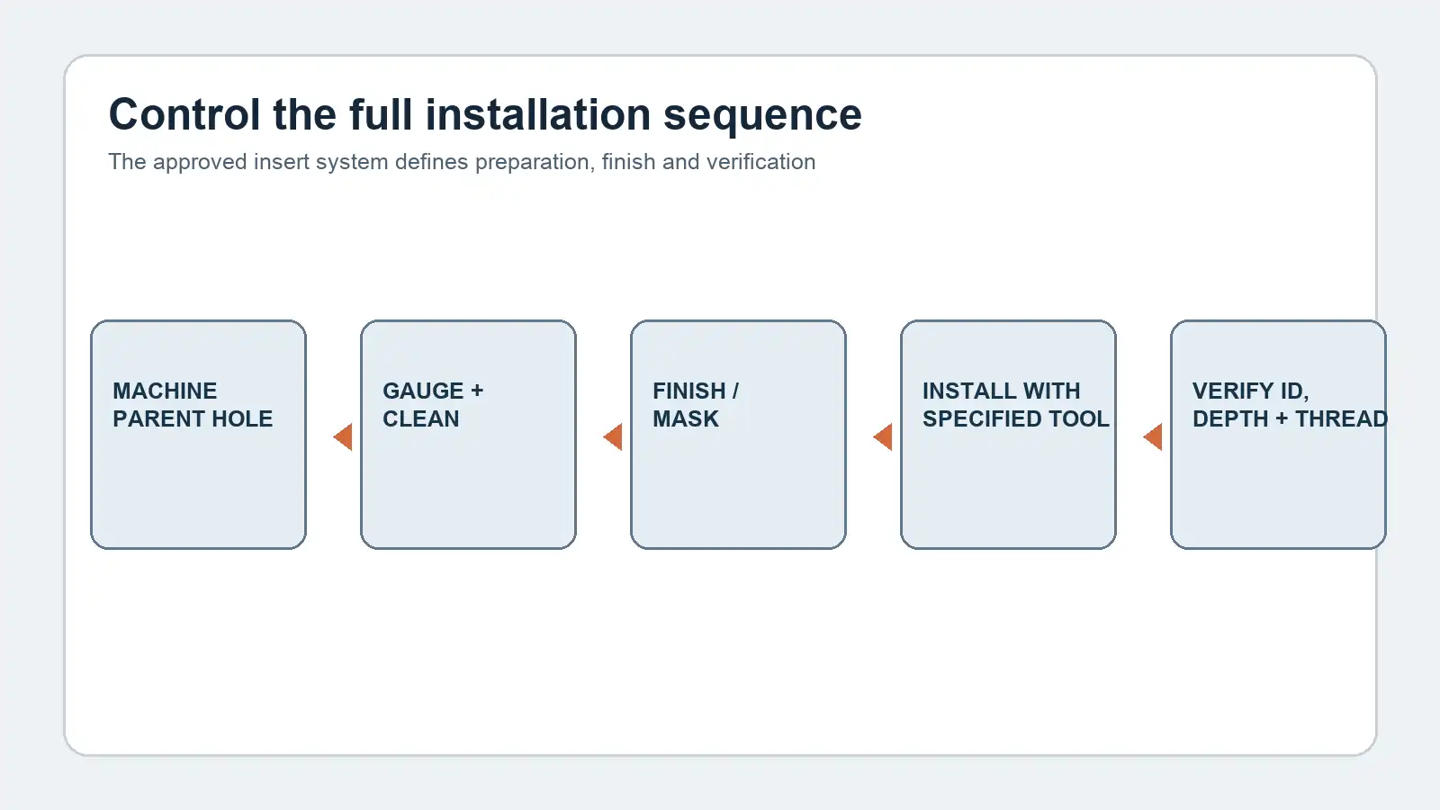
A typical controlled sequence may include machining and gauging the parent hole, cleaning, approved surface treatment or masking, final cleaning, insert installation with specified tooling, set-down verification and final thread/visual inspection. This is an example process logic, not a universal route.
If the insert is installed before finishing, verify that the chemical process will not damage or trap solution at the interface. If it is installed after finishing, account for coating in the preparation and protect the finished surface from installation damage. For hard-anodized components, see our drawing and masking guide.
Drawing and RFQ notes that remove ambiguity
Include:
- final internal thread designation and applicable thread system;
- insert manufacturer, family, part number and revision, or approved equivalents;
- insert length and quantity per part;
- installation side, depth or set-down limit;
- locking or tang-removal requirement when applicable;
- surface-finish sequence and masking instruction;
- corrosion-control or compatibility requirement;
- inspection, torque, proof-load or traceability requirement when function demands it;
- whether inserts are supplied by the buyer or manufacturer.
Do not model the insert as solid part geometry and assume the supplier will infer the commercial product. A bill of materials plus drawing callout is more reliable.
Installation access is a DFM requirement
Installation tools need axial access and enough room around the hole. Deep pockets, angled walls and nearby ribs can block the mandrel or key-driving tool even when a cutter reached the original hole. A bottom-side insert may require a second setup or manual operation.
For multi-face parts, show the installation direction and identify any sequence dependency with other components. Five-axis machining can improve hole access, but it does not eliminate manual installation clearance or inspection needs.
Inspection and acceptance
Inspection should verify what the joint needs:
- parent-hole size or special tapped-hole gauge before installation;
- correct insert part and length;
- installed depth or set-down;
- key engagement or tang removal where required;
- final internal thread acceptance using the specified method;
- visual evidence of damage, cross-threading or incomplete seating;
- proof load or installation torque only when an approved requirement defines it.
Do not invent a torque test during quoting. Torque values depend on the fastener, lubrication, insert, parent material and joint design. If load validation is required, the drawing or purchase order should define the method, sample size and acceptance limit.
Common mistakes
Calling out only the final thread
This omits the hardware, parent-hole process and installation state.
Mixing brands and tooling
Nominally similar inserts can use different preparation dimensions. Keep the qualified system together.
Ignoring trapped chemicals and galvanic couples
The insert, coating, fastener and environment interact. Specify the intended finish and consult the relevant finish and insert suppliers.
Installing into an undersized boss
The CAD envelope must include product-specific radial material and tool access, not only the final thread diameter.
FAQ
Are wire-thread inserts always stronger than tapped aluminum?
Not universally. Joint strength depends on insert length, parent material, bolt strength, geometry, installation quality and load. Use qualified design data for the selected system.
Should the insert be installed before anodizing?
There is no universal sequence. Consider masking, coating buildup, chemistry compatibility, electrical contact and installation damage, then document the approved route.
Can any standard tap make the insert hole?
Many insert systems require a product-specific thread form or tap. Follow the current manufacturer's preparation instructions.
What should a supplier report?
At minimum, confirm insert identity, quantity and installation acceptance. Critical programs may also require parent-hole inspection, set-down records, lot traceability or a defined proof test.
Final drawing check
Before release, verify that the selected insert is tied to the joint function, the exact hardware and preparation are controlled, blind-hole depth is complete, installation access exists, finishing sequence is explicit and the acceptance method is measurable. That turns “add insert” into a repeatable manufacturing requirement.






