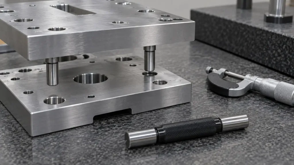
Dowel pins usually locate two parts; screws usually provide clamp load. That distinction makes a dowel hole more than a nominal diameter. The assembly depends on the limits of both the pin and hole, the intended removable or permanent fit, the relationship between paired holes, and the datums used to machine and inspect them.
This guide explains what to put on a drawing or RFQ for CNC-machined dowel pin holes without turning one fit label into a universal manufacturing promise.
Quick answer
Define whether each side of the assembly needs retention, accurate location or free assembly. Specify the actual pin standard and tolerance, the hole tolerance or ISO fit class, finished depth and lead-in, datum relationship, coating condition, and inspection evidence. Do not assume “reamed,” “H7” or “press fit” alone defines the complete assembly.
Choose the functional fit first
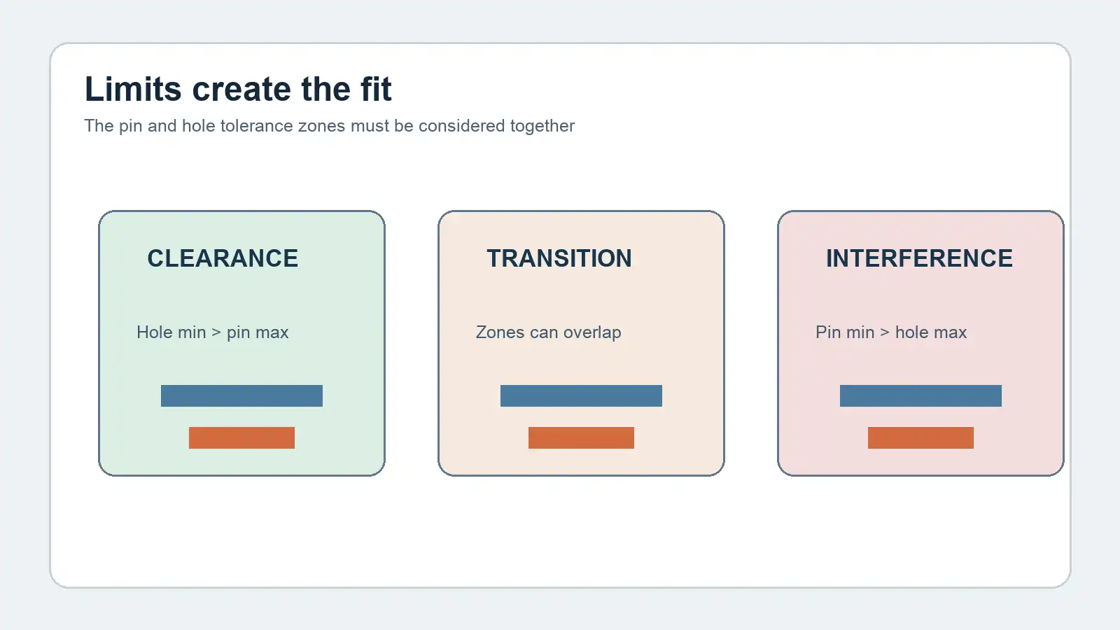
Three broad fit outcomes are useful in design discussions:
- a clearance or slip fit allows assembly and removal with space between worst-case limits;
- a transition fit can produce small clearance or interference depending on actual sizes;
- an interference or press fit retains the pin by elastic deformation and contact pressure.
ISO 286-1:2010 defines the ISO code system and the concepts behind basic-hole and basic-shaft fits. ISO 286-2:2010 provides standard tolerance classes and limit deviations. A fit designation must be interpreted at its nominal size and with the tolerance of both features. The same letter-number code is not a fixed micrometre value for every diameter.
Many assemblies retain the pin in one component and use a slip fit in the mating component. That approach supports repeatable location while allowing service disassembly. Whether it is appropriate depends on loads, materials, wall thickness, temperature, installation method and required positional repeatability.
Specify the pin, not only the hole
A drawing that calls out a hole but leaves the dowel pin undefined does not close the tolerance loop. State the pin diameter, tolerance class or product standard, material and condition when relevant. Purchased hardened ground pins can have a different tolerance from a turned custom pin.
The designer should also decide which part retains the pin, the insertion direction, engagement length and whether replacement is expected. In thin aluminum walls, aggressive interference can create high local stress, distortion or cracking. In dissimilar-material assemblies, temperature changes can alter interference because the components expand differently.
Avoid copying a press-fit allowance from an unrelated application. The required retention should be validated for the actual materials, diameters, surface conditions and service environment.
Size tolerance is not location tolerance
A hole can be the correct size and still be misplaced. Conversely, a well-located hole can be too small for assembly. Treat these as separate requirements:
- size controls whether the pin fits the bore;
- form affects contact and insertion behavior;
- orientation controls the hole axis relative to a datum surface;
- position controls the hole or pattern location relative to the datum reference frame;
- surface texture and edge condition affect installation and wear.
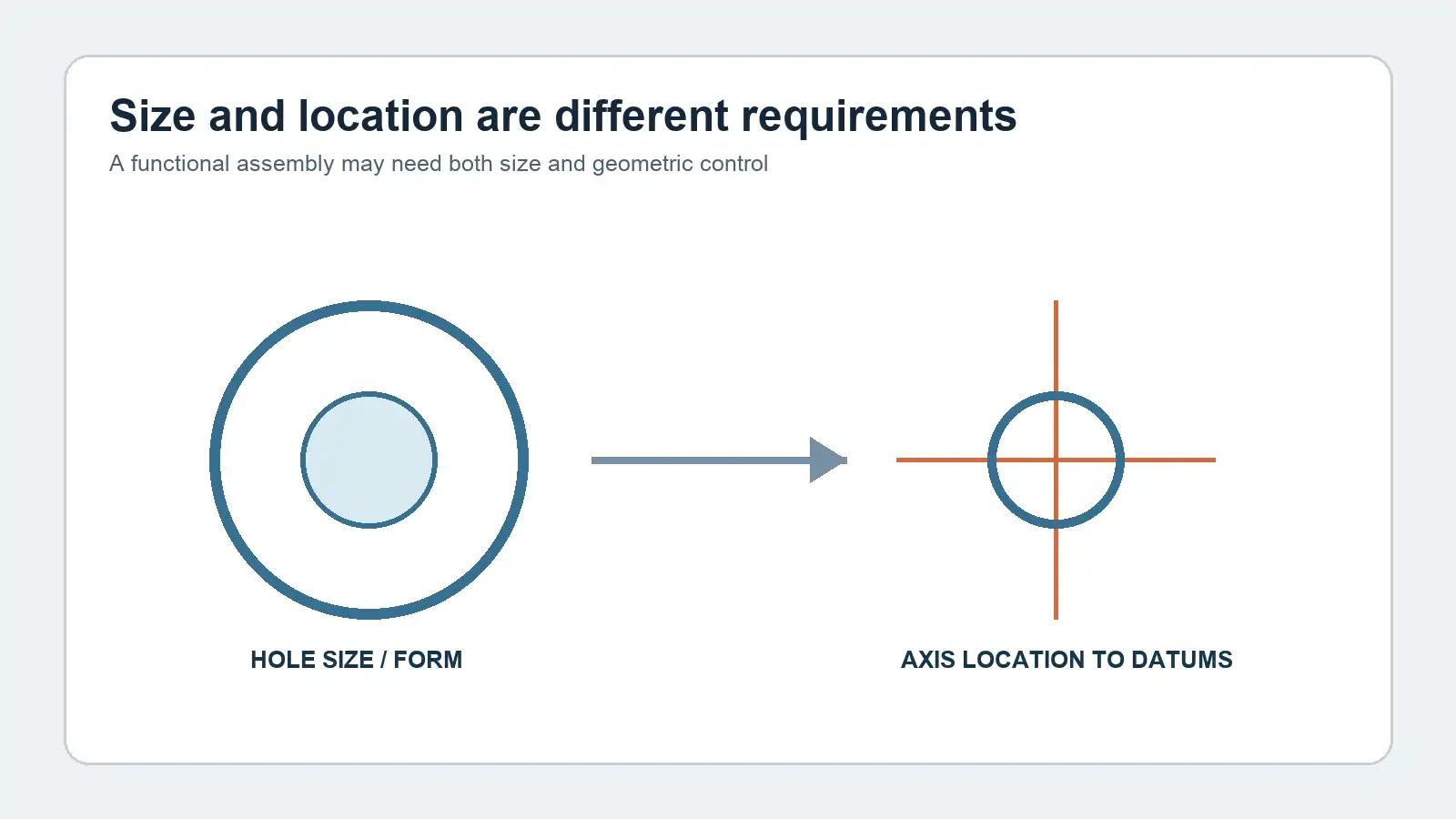
For a two-pin pattern, the hole-to-hole relationship and the pattern's relationship to mounting datums both matter. If the design uses ASME Y14.5, apply its datum and position rules consistently. If it uses ISO GPS, keep the ISO framework; do not combine symbols and defaults casually.
Coordinate plus/minus dimensions may describe location, but a functional position tolerance can communicate a cylindrical zone and datum relationship more directly. The choice belongs to the design authority, not to an SEO rule or a machine preference.
Drilling, boring and reaming are process choices
The final hole may be drilled, interpolated, bored, reamed, ground or produced by another controlled process. Reaming is common for close-tolerance dowel holes, but the word “ream” is not an acceptance requirement. Tool runout, stock allowance, hole straightness, material behavior, coolant, alignment and tool wear can all affect the result.
For blind holes, specify finished depth and provide clearance for tool geometry and chips. A dowel also needs a realistic insertion lead-in. A sharp burr or damaged edge can score a pin and change the apparent assembly force. Our blind tapped-hole guide addresses the related distinction between functional depth and drill-tip clearance.
Coatings require the same condition logic as any precision bore. If anodizing or plating reaches the hole, the finished size and texture can change. State whether the hole is masked, machined after finishing, or accepted after finishing with a defined final limit.
Inspection must match the question
No single gauge proves every requirement.
- a calibrated plug gauge can provide fast functional evidence for a size limit;
- an internal micrometer, bore gauge or air gauge can provide quantitative size data under suitable conditions;
- a CMM or optical system may evaluate axis location and orientation relative to datums;
- roundness or form equipment may be needed when bore form is function-critical;
- a functional assembly gauge can evaluate a pattern as used, if its design is controlled.
The measurement method, temperature, cleaning, coating condition and datum setup should match the drawing. ISO 1:2022 defines the standard reference temperature for geometrical and dimensional properties, but a practical inspection plan must still manage part and instrument temperature.
Avoid overconstraint in two-pin assemblies
Two identical round pins in two close-fit round holes can overconstrain an assembly when the center distance varies. Designers sometimes use one round locating feature and a relieved or diamond-shaped second feature so that the assembly controls the required degrees of freedom without binding along the less critical direction.
This is a design decision, not a blanket rule. Loads, repeatability, interchangeability and service needs determine whether relief is acceptable. The drawing should show the functional intent clearly enough that the supplier does not “correct” it into two ordinary round holes.
What to send with an RFQ
Provide the 3D model and controlled drawing, pin specification, desired fit for each component, assembly direction, material and heat-treatment state, coating or masking requirements, datum scheme, mating-part definition, lot size, and inspection/reporting requirement. For paired parts, identify whether the supplier will machine both components and whether interchangeability is required across the lot.
If the holes appear on different faces or operations, explain the functional datum relationship. Review multi-face datum schemes and probing versus CMM inspection when setup transfer or acceptance evidence is important.
FAQ
Is H7 always a slip fit for a dowel pin?
No. H7 defines a hole tolerance zone within ISO 286; the resulting fit depends on nominal size and the mating pin tolerance. Verify the full combination.
Does a reamed hole automatically meet position tolerance?
No. Reaming primarily addresses hole size and finish. Hole location and orientation depend on the preceding process, setup and geometric controls.
Should the pin be pressed into aluminum?
It can be appropriate, but interference, wall thickness, alloy condition, edge distance, installation force and service temperature must be evaluated for the actual design.
Can go/no-go gauges replace a CMM report?
They can efficiently verify a defined size or functional boundary, but they do not automatically report axis position, datum alignment or every geometric characteristic.
Final drawing check
Before release, confirm the pin limits, hole limits, retained and removable sides, datum relationship, depth and lead-in, final finish condition, and measurement plan. That closes the design-manufacturing-inspection loop and prevents a supplier from guessing what “dowel hole” means.






