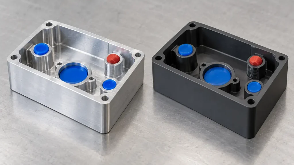
The featured visual is an AI-generated engineering concept, not a customer component, production photograph or inspection record.
Hard anodizing should be planned as part of the finished geometry, not added as a vague note after machining. A useful drawing identifies the governing specification, coating type and class, required coverage, masking boundaries, color or sealing requirements, and which dimensions apply after finishing. It also separates coating-thickness acceptance from finished-part dimensional acceptance. Without those decisions, the machinist, anodizer and inspector can each interpret the same note differently.
This guide explains how to prepare a CNC aluminum part for hard anodizing without assuming one universal film thickness, dimensional allowance or shop capability. The actual route depends on the alloy and temper, geometry, finish specification, functional interfaces, selected anodizing source and inspection plan.
Start with the governing hard-anodizing specification
“Hard anodize” is not a complete purchase requirement. In the U.S. defense specification system, the active MIL-PRF-8625 document listed by DLA ASSIST is Revision F with Amendment 2, dated 23 November 2020. It defines six coating types and two classes for non-architectural aluminum applications. Type III identifies hard anodic coating; Class 1 is non-dyed and Class 2 is dyed. Those labels do not by themselves define every requirement for a particular part.
ISO 10074:2021 is another current published specification for hard anodic oxidation coatings on aluminum and its alloys. Its official page states that it includes coating requirements, test methods and information the customer must provide to the anodizer. As of this review, ISO shows the 2021 edition at the close-of-review stage, so controlled documentation should identify the edition actually required and recheck status before release.
Choose the system required by the customer, contract or regulated application. Do not combine a MIL type/class callout with ISO acceptance language unless the responsible engineer has reconciled the requirements. If neither standard is contractually required, define a company or supplier specification that states the same practical information rather than writing only “hard anodize black.”
| Drawing decision | Why it matters | What to state |
|---|---|---|
| Governing document | Different systems use different classifications and tests | Standard number, revision or edition, and any approved exceptions |
| Type and class | Process family and dye condition affect the route | For example, the applicable Type III and Class 1 or 2 under MIL-PRF-8625 |
| Coating requirement | Thickness and acceptance affect dimensions and verification | Required range or minimum, location, and test method under the chosen specification |
| Seal, dye and appearance | These choices can affect color, wear behavior and acceptance | Required color, sealing condition and cosmetic limits, if functionally necessary |
| Coverage and masking | A whole-part note can conflict with threads, fits and electrical contacts | Coated, masked and optional areas shown on the drawing or controlled model |
| Final dimensions | The coating changes the physical surface | Identify which dimensions and geometric tolerances apply after processing |
Coating thickness and dimensional change are related but not identical
Anodizing converts aluminum at the surface and builds an oxide layer. Part of that layer develops into the base material and part extends beyond the original surface. The outward portion changes the final envelope, but the relationship is not a universal one-half rule. Alloy, temper, surface preparation, bath conditions, coating requirement, geometry and local current distribution can change the result.
For a single external surface, outward growth can shift the finished surface. For a slot or gap, coating on both opposing faces reduces the clear opening by the combined growth of both faces. A coated bore can become smaller; an external pin can become larger. Edges, recesses and current-shielded regions may not build identically to open surfaces. These mechanisms are why a designer should not simply subtract one nominal thickness from every machined dimension.
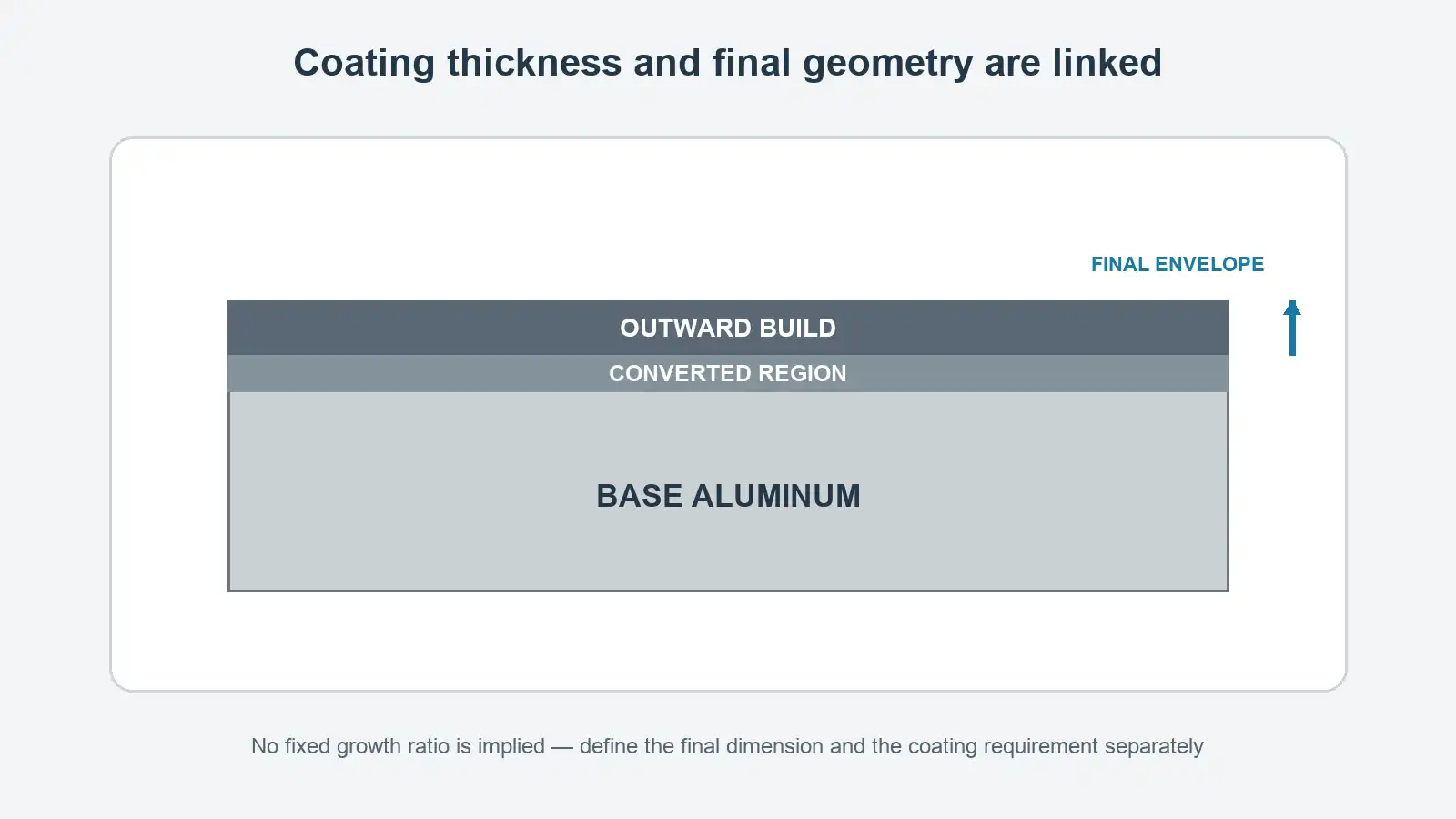
Treat coating thickness and final size as two linked requirements with separate acceptance logic. The anodizer may verify oxide thickness, while the machining supplier or final inspector verifies the functional dimension after finishing. If a fit, bearing seat, sealing land or precision datum must remain bare, masking may be more stable than trying to predict and compensate for coating on that surface. If it must be coated, the drawing should define the final requirement and the supplier should agree on the pre-finish target and process capability.
Map coated, masked and contact areas explicitly
Masking is a design input because it creates a boundary between coated and uncoated material. That boundary has location, edge condition and process limitations. A short note such as “mask holes” is ambiguous when a part has clearance holes, threaded holes, dowel bores, fluid passages and electrical contacts.
Use an annotated view or controlled 3D product definition to identify each category:
- surfaces that must receive the specified hard anodic coating;
- precision fits or datum features that must remain uncoated;
- electrical bonding or grounding areas that require conductive base metal;
- threads that must be masked, compensated or processed by an approved alternative;
- rack or electrical-contact areas allowed by the design;
- cosmetic boundaries whose position or edge quality matters;
- surfaces where coating is optional because masking access is impractical.
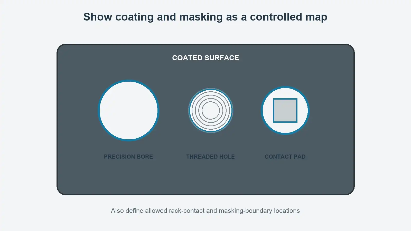
Hard anodic oxide is electrically insulating relative to bare aluminum. If electrical continuity is functional, the drawing should define the required contact area and its protection, not rely on the finisher to infer it. Rack contacts are also process necessities: current must enter the part somewhere. Their permitted location should be agreed where witness marks, bare spots or contact damage would affect appearance or assembly.
Masking is not infinitely precise. Plugs, tapes, paints and reusable fixtures have different edge capability, temperature resistance and access limits. Deep intersecting holes, blind cavities and very small features can complicate installation and removal. Ask the selected finishing source to confirm the intended masking method and achievable boundary before freezing a critical transition.
Decide how threads and fitted holes will be handled
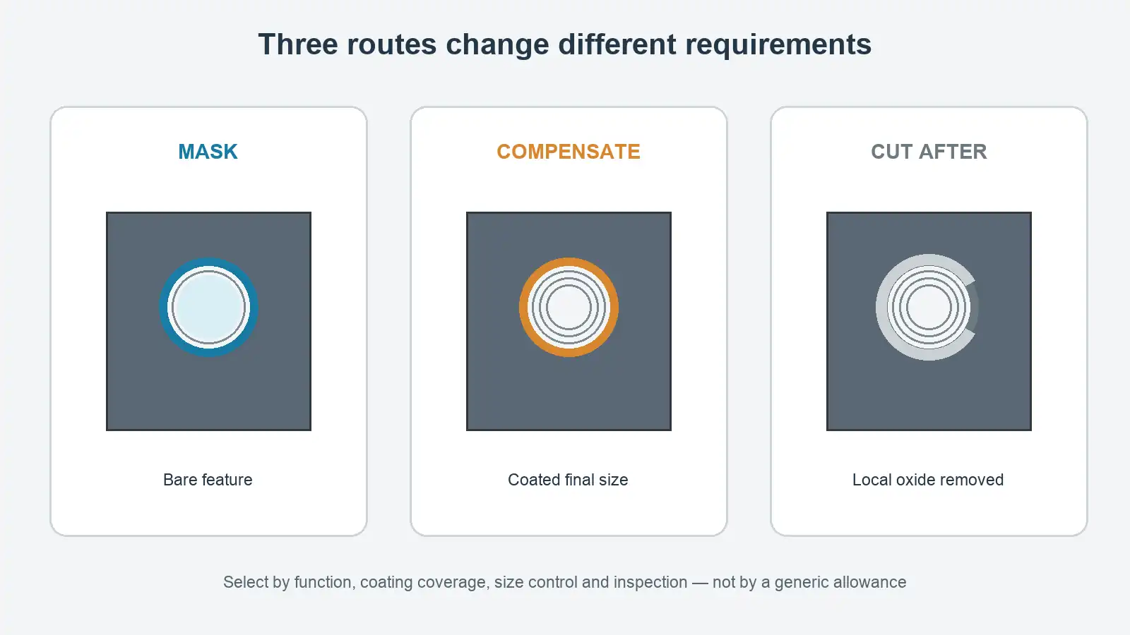
Internal threads and close-tolerance holes concentrate several risks: coating changes size, the oxide is harder and more brittle than the base metal, masking may leave an imperfect edge, and post-process cutting exposes bare aluminum. No single strategy is correct for every part.
Common options include:
- Mask the complete thread or bore. This preserves the machined size and conductivity of the protected surface, but the mask boundary and bare area must be acceptable.
- Machine a compensated pre-finish size and anodize the feature. This retains coating coverage, but compensation must be established with the actual alloy, process and supplier rather than a generic allowance.
- Finish-machine, ream or tap after anodizing. This can restore size but removes the protective oxide locally and may damage the coating edge. Use it only when the exposed surface is acceptable and the sequence is controlled.
- Use an insert or separate conductive interface. This can move wear or electrical function away from the anodized aluminum, but changes assembly and procurement requirements.
For mating threads, specify the final fit or functional gauge condition and whether it applies before or after anodizing. Do not assume that a conventional thread class automatically explains coating allowance, masking or acceptance. For dowel holes, bearing seats and seal bores, state the final dimension and geometric relationship to the datum system; a diameter alone may not protect alignment.
Put post-finish tolerances where function is evaluated
If the customer assembles and uses the part after anodizing, the drawing normally needs to control the finished condition of critical interfaces. That does not mean every dimension requires post-finish inspection. It means the product definition should identify which requirements are functional after coating and which are manufacturing controls before coating.
A practical control plan may include:
- incoming alloy and temper verification;
- pre-finish measurement of dimensions used for process compensation;
- confirmation of masking and rack-contact locations before processing;
- coating-thickness verification at defined representative areas;
- final dimensional and GD&T inspection on the finished part;
- thread gauge, assembly gauge or electrical continuity checks where applicable;
- visual inspection against agreed color, burn, stain and masking-boundary criteria.
Coating-thickness measurement also requires a defined method. ISO 2360:2017 remains current and describes amplitude-sensitive eddy-current measurement for non-conductive coatings on conductive non-magnetic base metals; its official scope notes particular applicability to many anodic oxide coatings. Instrument calibration, base material, part curvature, edge distance and measurement location still affect the result. The applicable product specification and inspection plan should control how readings are taken and accepted.
Dimensional measurement should occur after the part reaches a defined temperature and clean condition. Soft plugs, masking residue and seal deposits can interfere with contact measurement. A CMM can evaluate relationships among finished features, but it does not replace a suitable coating-thickness method or a functional thread gauge.
Account for alloy, surface preparation and appearance
Different aluminum alloys and tempers can respond differently in hard anodizing. Silicon, copper and other alloying constituents influence coating formation and color; welds, cast regions and dissimilar stock conditions may show visible variation. Machining marks, blasting, polishing, etching and chemical pretreatment also change the appearance beneath or through the oxide.
Therefore, a Class 2 dyed requirement does not guarantee a perfectly uniform cosmetic black across every alloy and geometry. If appearance is critical, define the viewing surfaces, allowable variation, surface preparation and approval method. A representative coupon processed with the production lot can help with communication, but it does not automatically prove thickness or dimensions on every feature of the part.
What to send with a hard-anodized CNC part RFQ
Send enough information for machining, finishing and inspection to be planned as one route:
- 3D CAD plus a controlled 2D drawing or annotated model;
- exact aluminum alloy, temper and permitted stock form;
- governing anodizing standard and edition or revision;
- Type/Class or the equivalent requirements under the selected system;
- coating thickness requirement and where it applies;
- dye, sealing, corrosion, wear or appearance requirements that are truly functional;
- annotated coated, masked, electrical-contact, thread and rack-contact areas;
- dimensions and GD&T requirements that apply after finishing;
- inspection method, sampling and documentation requirements;
- mating-part or gauge information for critical fits;
- quantity and any approved finish-source restrictions.
Use the CNC drawing review checklist to identify conflicting notes before quotation, and review complex multi-face access on the 5-axis machining service page. For a non-confidential review, send the controlled CAD, drawing and finish specification through the contact page.






