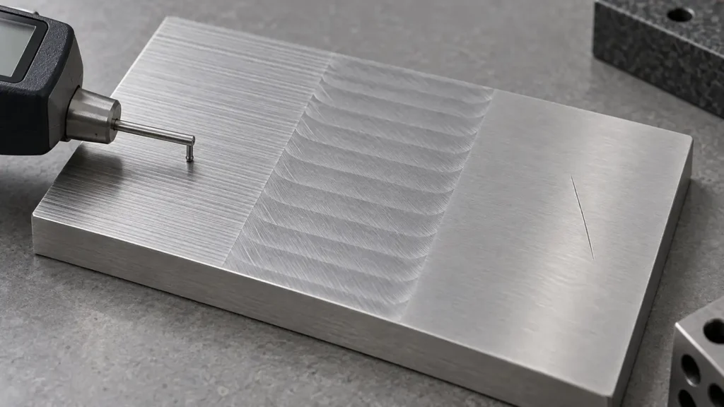
The featured visual is an AI-generated engineering concept, not a customer component, production photograph or inspection record.
Ra is one numerical description of a filtered surface profile; it is not a complete verdict on appearance, function or workmanship. Two CNC surfaces can report a similar Ra while showing different lay, spacing, waviness or isolated damage. A useful drawing therefore connects the required surface to its function, the applicable standard, the measurement direction and filtering conditions, plus separate controls for defects or visual appearance when those matter.
This guide focuses on acceptance decisions rather than reproducing a roughness conversion chart. It explains what designers, quality engineers and buyers should specify before a machined surface is quoted or inspected.
Surface texture contains more than roughness
ASME B46.1-2019 (R2026) defines surface texture through roughness, waviness and lay. In the ISO GPS system, ISO 21920 addresses profile surface texture: Part 1 covers indication on technical documentation, Part 2 covers terms and parameters, and Part 3 covers specification operators. These systems should be applied deliberately rather than mixed by copying an old symbol or default.
| Surface feature | What it describes | Why it can matter |
|---|---|---|
| Roughness | Relatively fine-scale profile variation after the specified filtering | Friction, sealing, coating, wear or appearance, depending on the interface |
| Waviness | Longer-spaced profile variation separated from roughness by the evaluation method | Contact distribution, sealing and apparent flatness over a local area |
| Lay | Predominant direction of the surface pattern | Directional sliding, sealing leakage paths, lubricant retention and appearance |
| Isolated imperfection | Scratch, dent, crack, pit or other localized event | May be unacceptable even if an average roughness result passes |
| Form and GD&T | Larger-scale geometry such as flatness, profile, location or orientation | Controls shape and feature relationships; it is not replaced by Ra |
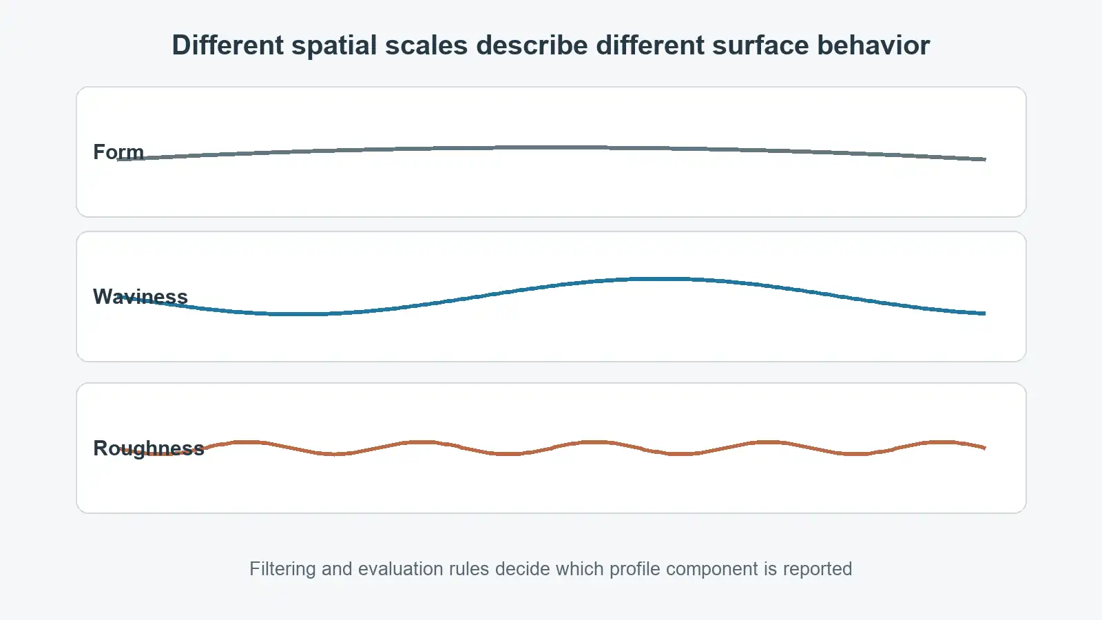
A surface can therefore have acceptable size and position but unacceptable texture. It can also have a low Ra and still contain a scratch across a sealing land. Conversely, visible regular tool marks are not automatically a defect if they match the specified process and functional requirement.
What Ra says—and what it leaves out
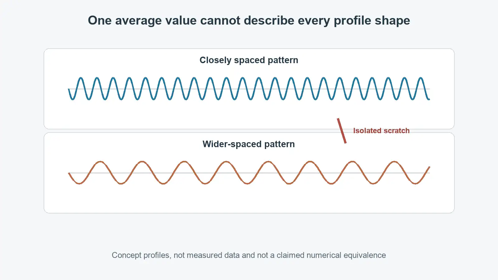
Ra is the arithmetic mean of the absolute deviations of a roughness profile from its mean line over the defined evaluation. Averaging makes it compact and useful, but it also reduces very different profile shapes to one number.
For example, one surface may contain many small, closely spaced peaks while another has fewer broader marks. If their averaged deviations are similar, Ra alone may not distinguish the functional difference. An isolated deep valley can also be diluted by a long evaluation length. Other parameters may be appropriate when peak-to-valley behavior, spacing, material ratio or another functional characteristic controls performance.
This does not mean that Ra is wrong. It means the parameter must be chosen for the interface rather than used as a universal quality score. Do not convert an Ra requirement to another parameter with a fixed multiplier and treat the result as equivalent; the relationship depends on the actual profile.
Tool marks carry process information, not an automatic pass/fail result
Milling, turning, grinding, lapping and other processes create characteristic directional patterns. In milling, feed per tooth, cutter geometry, runout, engagement, tool wear, vibration and machine motion can influence the resulting pattern. In turning, feed and nose geometry contribute to the helical lay. Built-up edge or chip recutting can add irregular features that the ideal geometric model does not predict.
Regular tool marks may be intentional and functionally acceptable. Irregular chatter bands, torn material, smeared edges or crossing scratches may indicate a different mechanism. Visual inspection can identify where to investigate, but appearance alone does not produce a traceable roughness value.
The process decision is not simply “slow the feed for a smoother part.” A finishing pass may reduce feed marks, but too little chip load can create rubbing; a longer tool can add vibration; a worn edge can change both texture and burr formation. Polishing can remove directional marks while rounding edges, changing flatness locally or embedding media. Every intervention should be judged against the functional surface and its downstream process.
Measurement direction changes the result
A profile instrument samples along a line. If the stylus crosses the lay, it usually encounters the machining pattern differently than if it travels parallel to it. The measurement direction should therefore follow the applicable drawing and standard rules, or be explicitly agreed when the surface has multiple or non-directional patterns.
The Mitutoyo roughness guide describes profile measurement normally taken at right angles to the lay of the machining marks. That is useful general guidance, but the part geometry may restrict stylus travel or make several directions functionally relevant. Small sealing lands, curved surfaces and interrupted features can require a specific fixture, stylus and evaluation plan.
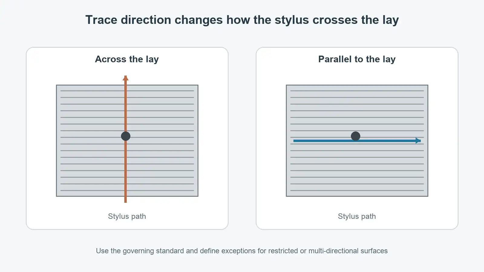
Record where and in which direction the trace was taken when that information affects acceptance. A single convenient trace on a large face may miss a local transition, tool entry region or isolated defect.
Cutoff, filtering and evaluation length are part of the requirement
The measured profile contains components at different spatial scales. Filtering separates the components treated as roughness from longer-wavelength behavior treated as waviness or form. Change the cutoff or evaluation conditions and the reported number may change even though the physical surface has not.
ISO 21920-2:2021 defines terms and parameters for profile-method texture, while ISO 21920-3:2021 specifies operators used to evaluate those requirements. The official ISO status pages show both 2021 editions as published but in revision stage as of this review, so a controlled drawing should identify the governing edition and company practice rather than rely on an undated internet chart.
For acceptance, confirm:
- the standard system and edition;
- profile parameter and limit;
- filter and nesting/index settings required by that system;
- evaluation length or any reduced-length exception;
- measurement direction and location;
- stylus or instrument limitations for the feature;
- acceptance rule and sampling plan.
If the surface is too short for the normal traverse, do not silently use a shorter trace and compare it as though nothing changed. Agree and document the alternative method.
Put the drawing symbol in a functional context
A surface-texture symbol should identify the applicable surface and requirement. It may also need process direction, machining allowance or other information under the chosen standard. Avoid applying one blanket roughness note to every face simply because the CAD model contains no surface annotations.
Start from the interface:
- Sealing land: consider whether lay could create a leakage path and whether isolated scratches need a separate limit.
- Sliding or bearing surface: consider direction, material ratio, lubrication and wear behavior rather than Ra alone.
- Bonding or coating surface: confirm the preparation and texture needed by the downstream process; “smoother” may reduce adhesion.
- Cosmetic panel: define visual zone, viewing conditions and defect limits separately from profilometer acceptance.
- Datum or mounting face: keep roughness distinct from flatness, profile and perpendicularity.
If only selected surfaces are critical, mark those surfaces. The remaining faces can follow a suitable general manufacturing note without inheriting the most expensive finish on the part.
Roughness, dimensions and GD&T answer different questions
Ra describes a filtered profile statistic. A size tolerance controls a feature’s size. GD&T controls form, orientation, location, profile or runout relative to its defined framework. None proves the others.
A bore can meet its diameter tolerance while having unacceptable texture for a seal. A ground face can have low Ra while failing flatness. A visually uniform milled surface can sit in the wrong position relative to the datums. Inspection plans must therefore map each requirement to a suitable method rather than use one instrument as a universal acceptance tool.
Contact profilometry is common for profile texture. Optical or areal methods may be useful for surfaces and features that cannot be adequately described by one line, but method correlation and the governing specification still matter. A CMM is generally aimed at geometry, not a substitute for a suitable surface-texture measurement system.
Machining and post-processing involve different trade-offs
The lowest roughness value is not automatically the lowest-risk choice. A tighter target can require a dedicated finishing tool, additional setup control, slower or more stable passes, inspection time and possible polishing or grinding. Post-processing can improve one texture metric while affecting edge definition, dimensions or local form.
Discuss the complete chain:
- What function does the surface perform?
- Which texture characteristic controls that function?
- Can the CNC process create the required condition with accessible tooling and stable workholding?
- Will coating, anodizing, grinding, blasting or polishing alter the surface afterward?
- How will the final state be measured and sampled?
Where the requirement applies after a secondary process, say so. A pre-coating Ra measurement does not automatically establish the final coated surface condition.
What to send with an RFQ
Include the controlled model and drawing, then identify:
- governing surface-texture standard and edition;
- parameter, limit, symbol and exact surfaces;
- required lay or process direction where functional;
- measurement direction, location and evaluation conditions when not left to a valid standard default;
- separate visual, scratch, dent or cosmetic criteria;
- whether acceptance is before or after coating or another finish;
- associated size, GD&T and datum requirements;
- mating component, sealing, sliding, bearing, bonding or cosmetic function;
- prototype and production sampling or report requirements.
If the requirement came from a legacy drawing, flag that context. ISO 1302:2002 and ISO 4287:1997 are withdrawn and were superseded in the ISO profile system; a legacy contract may still call them up, but it should not be silently rewritten or mixed with ISO 21920 defaults. For ASME work, ASME B46.1-2019 (R2026) is the current reaffirmed surface-texture reference shown by ASME at this review date.
Define acceptance before asking for a smoother number
A defensible surface requirement connects function, texture parameter, lay, measurement conditions and defect criteria. Ra is valuable when it is the right parameter, but it cannot stand in for the entire surface or for dimensional and GD&T acceptance.
Before release, ask the supplier to review the critical surfaces, machining access, finishing sequence and inspection method together. JIZAO can review these questions against a non-confidential drawing, but no universal roughness capability is implied without the actual material, geometry, process and measurement plan. See our CNC drawing review guide, GD&T and CMM planning guide, or contact JIZAO to discuss the requirement.






