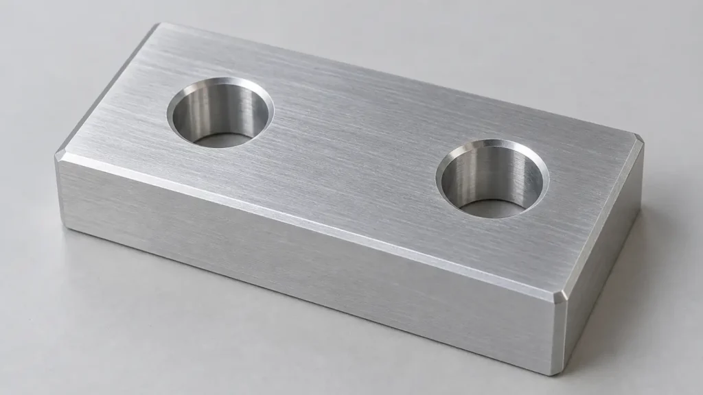
AI-generated conceptual engineering visual of a machined block. Not a JIZAO part, production photograph, or verified deburring result.
For CNC parts, specify the required edge condition, not just the instruction to deburr. Separate ordinary burr removal from a controlled chamfer or radius, and identify functional edges that must not be rounded indiscriminately. Before accepting a quote, agree which edges are included, what material removal is permitted, and how the finished condition will be checked. There is no universal edge-break size that suits every part.
This guide is for drawing and RFQ preparation. It does not prescribe a deburring process, certify a burr-free result, or replace the drawing owner’s engineering approval.
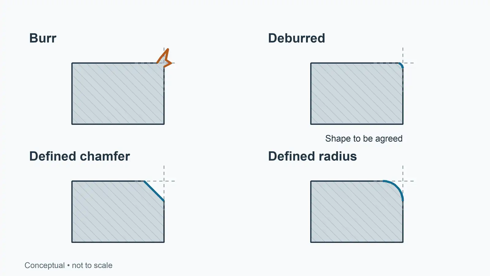
Burr removal and edge geometry are different requirements
A chamfer is a flat bevel; a rounded edge has a different geometry. Neither term should be used as a substitute for an undefined instruction to make a part safe to handle. Protolabs’ edge-design explanation illustrates this distinction, but its example dimensions and included services are supplier-specific, not a JIZAO default.
The distinction also matters in documentation. The ISO 13715:2017 abstract addresses edges of undefined shape and distinguishes them from geometrically defined edges, which use general dimensioning principles. This article does not reproduce the standard’s symbols or interpret its full requirements. Use the applicable controlled standard when creating a drawing notation.
Start the drawing review with three separate groups:
- General edges: identify where burr removal is required and agree the permitted resulting condition.
- Defined edges: dimension the chamfer or radius, including its applicable tolerance and extent.
- Protected functional edges: identify exceptions to the general note and define what must remain unchanged.
Define the exceptions before applying a general note
An instruction such as “deburr all edges” does not tell a supplier whether an assembly lead-in, a sealing boundary, and an ordinary handling edge may be treated alike. A useful drawing makes those differences visible rather than leaving the operator to infer them.
For each exception, ask: what does this edge do in the assembly? Which adjoining face, diameter, or contact region must remain within its requirement? Is a specific transition needed, or only removal of unwanted material? If the answer is unknown, mark the issue for design review instead of allowing an undocumented shop-floor decision.
An exception is not permission to leave a burr. It is a request to reconcile burr removal with the edge’s function. The drawing owner should approve that reconciliation before production.
For example, consider a hypothetical bracket with a hole used for assembly alignment. A general edge note and a separately specified hole-entry feature should be reviewed together. The supplier should not silently substitute a larger lead-in because it is easier to finish. This is an illustrative review question, not a customer case or a recommended dimension.
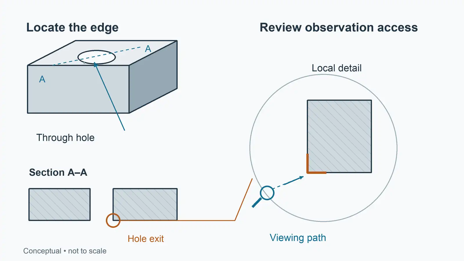
Include edges that are difficult to see
Review the underside, hole exits, recessed features, and any internal intersections relevant to the design. A photograph of the top face cannot establish the condition of an inaccessible edge. Ask the supplier to identify how the specified areas will be reached and how conformity will be demonstrated.
Separate these two questions in the RFQ:
- Can the proposed process reach the required edge without altering a protected feature?
- Can the agreed inspection method assess the required condition after processing?
An answer to the first is not automatically an answer to the second. Where access or inspection is uncertain, request a marked-up drawing with the unresolved location. Do not replace an unresolved requirement with a broad claim that all edges will be perfect.
Multi-face access may be relevant to a five-axis machining review, but the machine’s axis count alone is not a deburring acceptance criterion.
Agree on acceptance before comparing prices
A useful quote states its assumptions. Ask the supplier to acknowledge the edge note, list excluded or inaccessible locations, and flag any proposed change. If a particular process is mandatory, state it; otherwise distinguish the required outcome from a preferred method.
The inspection agreement should identify the locations, applicable acceptance requirement, method, and record needed. A general visual review and measurement of a defined chamfer are different tasks. Where magnification, sampling, cleanliness verification, or an inspection record matters to the application, have the responsible engineer specify it rather than adding arbitrary values to the RFQ.
Keep this agreement consistent with the overall inspection plan. An inspection report should address the actual requirement, not substitute unrelated dimensional measurements for edge-condition evidence.
A concise RFQ checklist
Before sending the package, confirm that it includes:
- The controlled drawing revision and matching part model.
- A general edge requirement with clearly identified exceptions.
- Dimensions and tolerances for any defined chamfers or radii.
- Functional faces and edges that need protection.
- Internal or hidden locations requiring particular attention.
- Relevant finish, cleaning, and inspection requirements.
- A request to flag conflicts or assumptions before manufacture.
Ask for drawing clarification whenever the model, general note, and local callout disagree. A supplier’s standard finishing practice is useful context, but it should not silently override the accepted drawing.
Prepare the edge requirements for review
The most useful starting point is a marked-up drawing showing general edges, defined transitions, and protected exceptions. Request a drawing review with those locations identified and ask which questions must be resolved before quotation. Process suitability and acceptance remain subject to review of the material, geometry, drawing, and inspection requirements.






