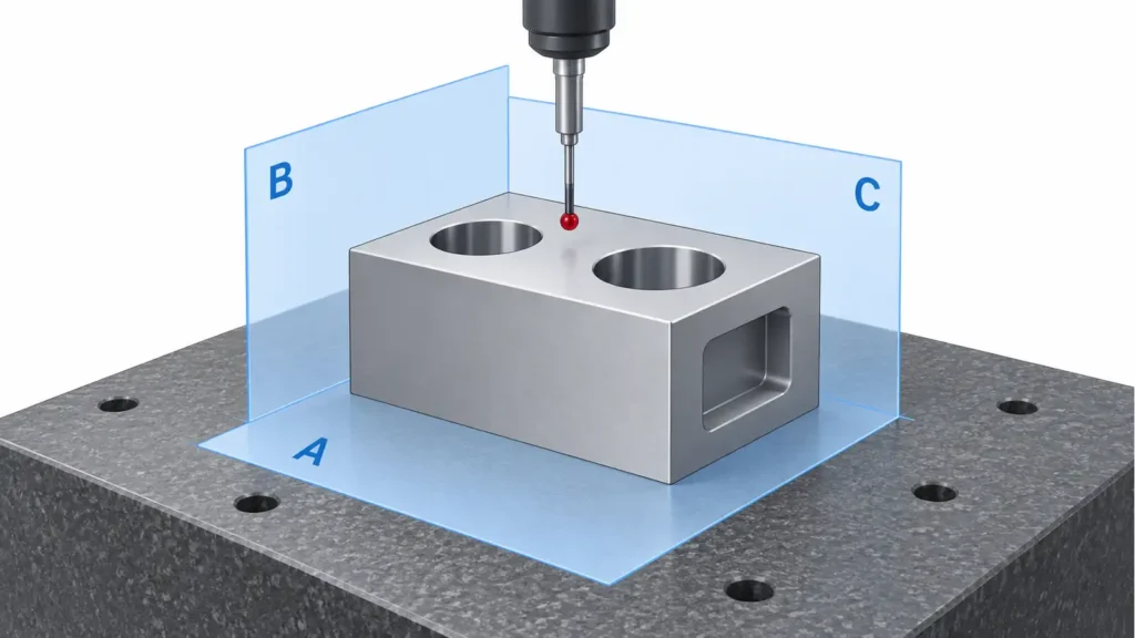
Short answer
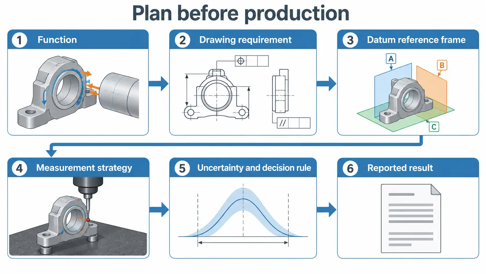
Plan inspection before production by linking each functional requirement to the drawing standard, datum reference frame, measurement method, sampling strategy, analysis algorithm, and acceptance rule. A calibrated or reverified CMM demonstrates machine-level performance under defined tests; it does not automatically establish the uncertainty of every measurement task. For multi-face parts, align to the specified datums in precedence order, preserve their constraints, and use best-fit analysis only for a justified purpose. Remember that flatness is a form control with no datum reference.
Start with function and the drawing—not the CMM
The inspection plan should answer a product question: does the manufactured part satisfy the stated requirement? The CMM is one tool for answering it. If the drawing leaves the functional relationship ambiguous, sophisticated software cannot recover the missing design intent.
Begin with the controlled drawing revision, the stated dimensioning and tolerancing standard, material and process condition, and any agreed acceptance rules. For US programs, that standard may be an identified edition of ASME Y14.5; international programs may reference ISO GPS standards such as ISO 1101. Do not mix conventions silently. ASME maintains the Y14 standards family, including Y14.5, while ISO lists ISO 1101:2017 as the published geometrical tolerancing standard at the time of this draft (ASME Y14 standards; ISO 1101). The contract drawing must identify which requirements govern the actual part.
Then translate assembly and performance needs into characteristics. Which face seats the component? Which bores locate mating hardware? Which surface seals? Which profile controls clearance? Those questions should drive datum selection and tolerances. Choosing datums because they are easy to probe can produce a convenient report that does not represent the part’s functional interface.
Create a characteristic-to-method matrix
Ballooning a drawing is useful only when each identifier leads to a defined verification method. Build a matrix before the first production lot. At minimum, include the characteristic, controlling requirement, datum reference frame, part state, equipment, access or stylus plan, point or scan distribution, evaluation method, uncertainty consideration, sampling frequency, report output, and responsible reviewer.
| Characteristic type | Planning question | Common risk to control |
|---|---|---|
| Size | What local or calculated size definition does the selected standard require? | Reporting a software default without matching the drawing definition |
| Position | Which datum reference frame and material-boundary conditions apply? | Replacing datum precedence with a global best fit |
| Profile | Is the tolerance unilateral, bilateral, or unequally disposed, and which datums apply? | Sparse data missing local deviation or the wrong alignment changing the result |
| Flatness | What surface state and sampling distribution represent the full controlled area? | Referencing a datum even though flatness itself has no datum |
| Perpendicularity or parallelism | Which datum establishes orientation? | Treating the result as independent form rather than a datum-related control |
| Runout | How will the datum axis be established, and can the part rotate or be sampled adequately? | Inadequate axis definition or access |
The matrix should expose impossible or weak checks while there is still time to change the design, process, fixture, or inspection approach. If a deep feature cannot be reached with a suitable stylus, an alternative sensor, sectional inspection, functional gage, or design change may be needed. “CMM inspection required” is not a complete method.
Build the datum reference frame in precedence order
A datum reference frame constrains the part’s degrees of freedom. Hexagon’s alignment overview describes a DRF as fixing the part in three-dimensional space and identifies primary, secondary, and tertiary datums as the features used to establish the alignment (Hexagon alignment overview). The essential point is precedence: once the primary datum has established its allowed constraints, a lower-precedence datum should not re-optimize those constraints away.
On a multi-face part, it is common to perform a rough or iterative alignment first so the probe can find the component safely. That navigation alignment is not necessarily the final evaluation alignment. The final calculation for a datum-controlled characteristic must represent the specified datum features, order, modifiers, and applicable standard.
Fixture design affects this process. The fixture must support the part without distorting it, provide access to required datum and measured features, and maintain safe probe clearance. If the part is measured in a restrained condition, that condition must be specified or agreed. Otherwise, a fixture can hold an out-of-form surface into a better result.
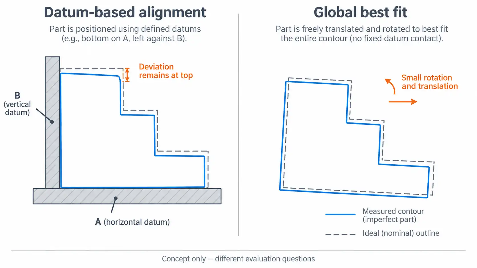
Do not use a global best fit to hide datum error
Best-fit alignment is valuable for some tasks: diagnosing an overall pattern, comparing a freeform surface when the specification permits it, or visualizing process drift. It is not a universal substitute for a drawing-defined datum reference frame.
A global best fit redistributes deviations to minimize a selected objective. That may make a color map look balanced while moving the coordinate system away from the functional datums. Position, profile, orientation, and runout results can then answer a different question from the drawing.
Even within datum evaluation, software algorithms require deliberate selection. Hexagon’s technical documentation explains that plain least-squares datum computation can differ mathematically from a measured datum simulator and that datum precedence constrains later datums from moving higher-precedence datums (Hexagon datum-solving guidance). Because this source documents a particular software generation, the current metrology team must confirm the applicable standard, current software behavior, filtering, fitting method, and validation before release.
Flatness has no datum; orientation controls do
Flatness controls the form of one surface. Its tolerance zone consists of two parallel planes separated by the stated tolerance; no datum is required. Mitutoyo’s metrology guide illustrates this distinction and separately shows perpendicularity as an orientation control related to a datum (Mitutoyo precision measurement guide).
This matters when a mounting face must be both flat enough to seat and oriented correctly to another interface. Flatness alone does not control that orientation. The drawing may require a separate parallelism, perpendicularity, or profile control tied to a datum, depending on function and the governing standard. Do not report a datum-aligned orientation deviation under the label “flatness,” and do not add a datum to a flatness requirement in an inspection plan.
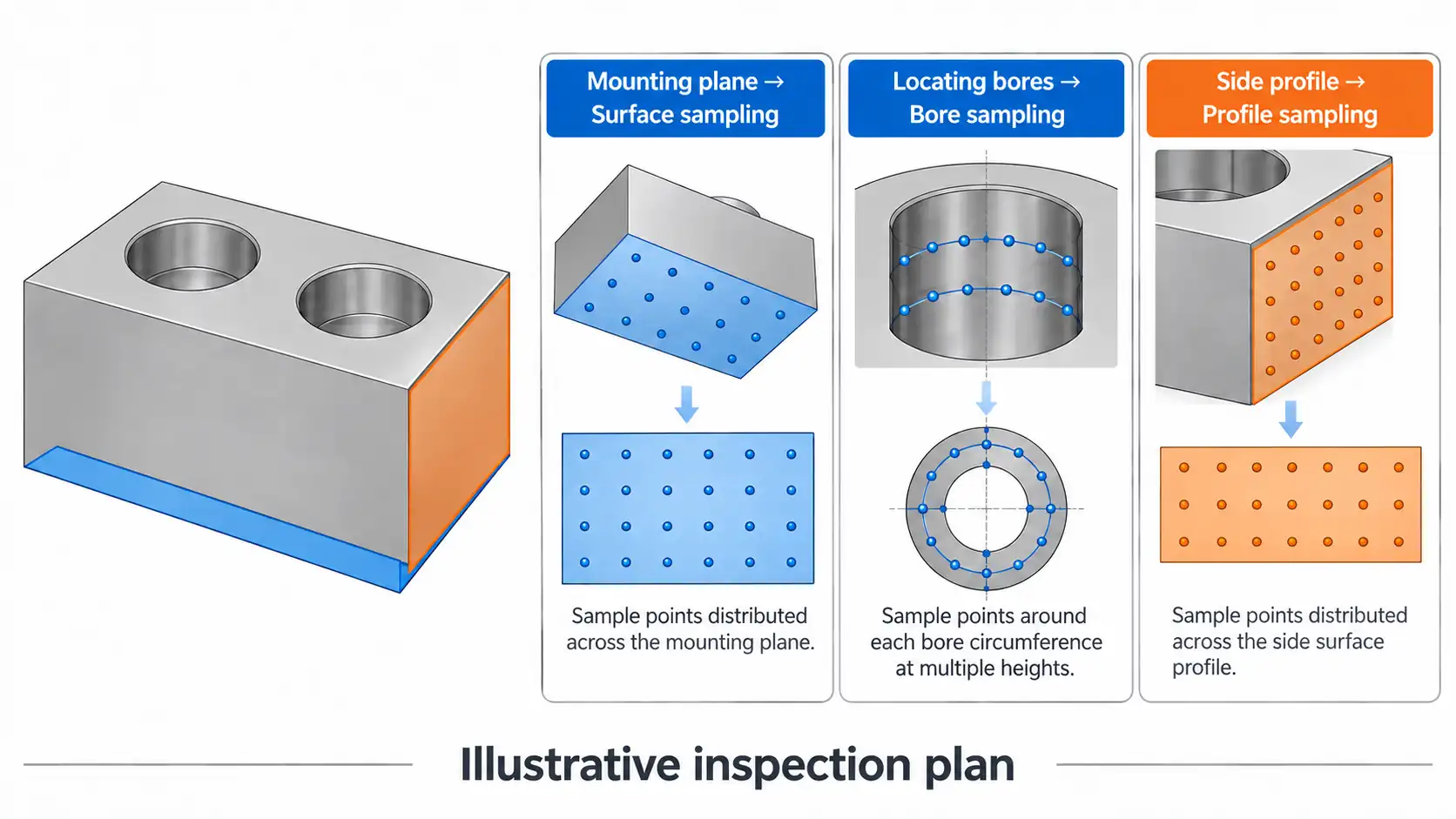
Sampling also matters. A few points can underrepresent waviness, edge lift, local damage, or a saddle-shaped surface. The plan should state the distribution of points or scan paths, excluded edge zones if justified, filtering, outlier treatment, and fitting method. More points are not automatically better if access, surface texture, contamination, or probe configuration introduces other errors; the strategy must represent the measurand.
Machine calibration is not task-specific measurement uncertainty
CMM acceptance testing, reverification, and calibration provide essential evidence about the measuring system. ISO 10360 is a series for CMM acceptance and reverification testing, as summarized by ZEISS (ZEISS ISO 10360 overview). Those results do not, by themselves, state the uncertainty for every characteristic on every part.
Task-specific uncertainty depends on the actual measurement. Contributors may include machine geometry, probe configuration and qualification, stylus bending, scanning dynamics, environmental and part temperature, fixturing, surface condition, sampling, filtering, fitting algorithms, access, operator choices, and the relationship between the measured points and the intended measurand. The UK National Physical Laboratory’s good-practice guide specifically addresses methods for determining task-specific CMM measurement uncertainty with reference to ISO 15530 (NPL CMM uncertainty guide).
The tighter the requirement and the higher the decision risk, the more important it is to define how uncertainty affects conformity. The inspection plan should identify the governing decision rule, any guard band, customer-specific quality requirement, and the party authorized to resolve an indeterminate or disputed result. A machine specification should never be copied directly into a report as though it were the uncertainty of the measured characteristic.
Plan access, probing, and reporting before production
Multi-face parts often require stylus changes, articulated probe positions, rotary-table moves, or multiple local measurement sequences. Simulate access when possible. Check for collisions with clamps, walls, and the part; qualify all needed probe configurations; and ensure datums remain measurable after the complete manufacturing process.
The report should make the result traceable without overwhelming the reader. Include at least:
- part and drawing revision under the approved confidentiality process;
- characteristic identifier and nominal requirement;
- datum reference frame and applicable modifiers;
- actual measured value and units;
- pass, fail, or other agreed conformity status;
- measurement equipment and program revision as required by the quality system;
- relevant part state, fixture state, and environmental condition;
- uncertainty or decision-rule information where required;
- deviations, concessions, or review disposition authorized by the responsible person.
For a first article or process validation, compare the inspection plan with how the part was located and machined. If related features were created in different setups, include characteristics capable of revealing transfer error. If the part is thin or flexible, verify whether free-state or restrained-state requirements apply. If a feature is inaccessible, resolve the gap before accepting production—not after a report is due.
A pre-production review checklist
Before releasing the inspection plan, ask:
- Is the drawing revision and governing GD&T/GPS standard explicit?
- Do the selected datums represent functional assembly contacts?
- Are datum precedence and material-boundary conditions implemented correctly?
- Is the navigation alignment separated from the final evaluation alignment?
- Is any best-fit use clearly justified and kept from masking datum error?
- Are flatness and datum-related orientation reported as different requirements?
- Do sampling, filtering, fitting, and stylus choices represent the measurand?
- Can the fixture support the part without changing the condition being evaluated?
- Has task-specific measurement uncertainty been considered for critical decisions?
- Are the conformity rule, report fields, and human approval path defined?
Conclusion
A defensible CMM plan makes a transparent chain from product function to the reported result. Select functional datums, apply them in precedence order, and define access, sampling, analysis, uncertainty, and conformity decisions before production. Treat calibration and reverification as necessary machine-level evidence, not a substitute for task-specific uncertainty. Use best fit for a documented purpose, never to erase datum-related variation, and keep flatness separate from orientation to a datum.
Ask about a non-confidential engineering question: Share only the broad part category, drawing-standard family, feature categories, quantity band, and inspection-planning question. Do not send drawings, report files, links, exact dimensions or tolerances, customer identifiers, or other confidential details through the current form. Arrange an approved secure channel before exchanging controlled technical files.






